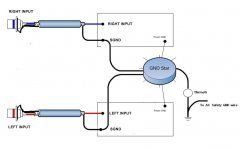
I would connect the shield to the chassis at the RCA end, and leave it unconnected at the PCB
I would connect the shield to the chassis at the RCA end, and leave it unconnected at the PCB
That's what I'm doing (as stated above). Thanks.
Ginum:
I'm not sure about your drawing- What exactly is that represented by the arrow in your diagram?
-Chas
Attachments
clm811 said:
That's what I'm doing (as stated above). Thanks.
Ginum:
I'm not sure about your drawing- What exactly is that represented by the arrow in your diagram?
-Chas
Not what you said. You said you were connecting shield to black on RCA, and that you had an isolated RCA. I'm saying connect the shield to chassis, not the RCA.
Sorry, I must have read your post incorrectly. Thanks for clarifying.
Hopefully this thing will work without humming...
Anyone else have photos of your progress?
-Chas
Hopefully this thing will work without humming...
Anyone else have photos of your progress?
-Chas
connect the shield to the chassis at the RCA end, and leave it unconnected at the PCB
and label both ends, "grounded shield" or "floating shield"That's what I'm doing
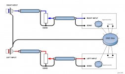
is that cable shielded twisted pair?The input cable I've chosen is a shielded, symmetrical twin-conductor (red for positive, black for negative plus a shield with drain wire).
The twisted pair gives the main attenuation of interference, both magnetic field and electrostatic field.
The shield gives a little attenuation of electrostatic field only and non for magnetic field.
If it's a parallel pair with a shield you are wasting your time. Get unshielded twisted pair (UTP).
...label both ends, "grounded shield" or "floating shield"
I believe with my hookup the RCA input end is "grounded shield" and PCB end "floating shield". Thanks also for helping to clarify.
...is that cable shielded twisted pair?
Yes,
thanks all!
-Chas
p.s.
Is anyone else close to finishing their amp(s)?
clm811 said:Sorry, I must have read your post incorrectly. Thanks for clarifying.
Hopefully this thing will work without humming...
Anyone else have photos of your progress?
-Chas
If you have humming, it is not likely to be due to this shielded input connection. In fact, unless this line is long and comes near the power cable or transformer, this line should not be an issue. As Andrew said, the twisted pair should provide most of any rejection.
Keep that line away from power lines and the transformer. If they cross, try to cross at 90 degree angles. This will be the the most likely cause of any humming from WITHIN the chassis, and the shield will do little or nothing to stop that.
The shield would only be effective for RF radiation, and the grounded chassis should keep that out, except for any from the bridge rectifier.
If you have any humming after that, and you connected everything as Leach specifies, your most likely cause would be a ground loop via the preamp, especially if it has a grounded chassis. If you get humming, follow Leach's instructions on his web site under the construction link to rectify it.
Chas,
It is also good pratice to twist the power wires coming from the caps to the pcb solder pads.
On this particular board layout the signal in to the board is a long distance from the signal/speaker out. I chose to route this signal wire under the board and keep it away from the power traces and output trace. It can be tedious but if you lay everthing out nice and neat you should not have anything but music in your speakers. The overall design yields a superbly quiet amplifier. Even at full volume there is no hum or hiss at the speakers.
Now go and get some kick--- music and see if you can rip out the cones on a set of 15 inch woofers. It is easier than you would think. I had no trouble. You now have a world class amplifier. Brag and feel proud. Most of your friends will not know just how nice these units are.
Have fun Tad
I am feeding my gnd mono amp from center ground (which Is connected to middle point of psu filter caps) and I got hum at open loop at the input
If I short input with gnd - no hum
If I short the gnd of input with heatsink - no hum
what could be the problem
If I short input with gnd - no hum
If I short the gnd of input with heatsink - no hum
what could be the problem
Samoloko,
where is the ground from the wall plug connected to your amplifier? Did you use the center tap on your transformer? If so where is it connected? Tad
where is the ground from the wall plug connected to your amplifier? Did you use the center tap on your transformer? If so where is it connected? Tad
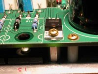
You need to isolate the transistor from the heat sink, as it is connected to the rail. A far better solution is to use a u shaped heat sink under the transistor and lose the post.
Pictures, please?
Guys,
Anyone else have progress pictures to share?
Tad (I know you've got a couple already built- care to post a picture or two)?
-Chas
P.S. Amp's been sitting untouched for a few weeks, as I'm working again. I hope to bring it over to a friend's place for a "smoke test" and to set the bias using his scope...
or use a To126 device as the driver and the heatsink then mounts on top of the device and the plastic case of the device is in contact with the PCB.
Problem goes away.
Problem goes away.
Note of Caution
Hi Guys!
A word of caution for anyone planning on using those neat (Aleph) power supply boards from BrianGT:
http://www.briangt.com/gallery/aleph-pcb/ps_pcb
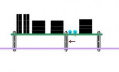
It's a good idea to insulate these boards from the chassis, using nylon standoffs, nylon washers and maybe even nylon screws as well.
While doing final testing for shorts before powering the Leach boards I noticed that even with (tapped) nylon standoffs and short screws coming in from top and bottom(see drawing), I was getting a short between one of the rails and ground. I traced it to one of the mounting screws. A metal washer was barely cutting through the paint on the board covering the edge of a trace and it so happened that very screw that was a tiny bit longer than the others, due to some flashing on the end, which just made contact with the bottom screw, grounding to the chassis. I had tested everything before "torquing" all screws down during final assembly and it was fine... 😱
Just another example that the "Devil is in the details" !
-Chas
Hi Guys!
A word of caution for anyone planning on using those neat (Aleph) power supply boards from BrianGT:
http://www.briangt.com/gallery/aleph-pcb/ps_pcb
It's a good idea to insulate these boards from the chassis, using nylon standoffs, nylon washers and maybe even nylon screws as well.
While doing final testing for shorts before powering the Leach boards I noticed that even with (tapped) nylon standoffs and short screws coming in from top and bottom(see drawing), I was getting a short between one of the rails and ground. I traced it to one of the mounting screws. A metal washer was barely cutting through the paint on the board covering the edge of a trace and it so happened that very screw that was a tiny bit longer than the others, due to some flashing on the end, which just made contact with the bottom screw, grounding to the chassis. I had tested everything before "torquing" all screws down during final assembly and it was fine... 😱
Just another example that the "Devil is in the details" !
-Chas
Attachments
6 transistor leach
I emailed Jens, but so far no reply.
I've got the 6 transistor Leach PCB, 7.4.6 (2005).
The parts are here-
6 transistor leach parts
(it does not look like the list was quite finished!)
But a number (R26, R34, R68, R69 and R41,R42,R43,R60,R61,R62,R28,R30) are "to be defined".
1. What are the values for these?
2. Also are MJL21195/96 suitable for output transistors? (I have many of these)
3. What voltage should I use for the DC rails to drive 4 ohm speakers?
- thanks
1. These are protection circuit resistors. Their values depend on the output devices chosen, the load and the rail voltage. Somewhere in this thread is a discussion of how to choose them. You can omit if you are brave and test the amp with inexpensive speakers before using your good ones. This isn't good practice, though.
2. Perfectly fine choice, rather rugged.
3. Again it depends on your output device selection and heat sinking, but with three pairs of MJL2119x you should be OK with 50-60V rails if the load is fairly non reactive and the impedance doesn't dip far below the 4 ohm nominal rating. The more reactive and lower the load dips, the lower your rails should be.
Better heat sinking means that the output devices won't get as hot and you'll be able to push them harder. With smaller sinks lower rails are appropriate.
For really rugged 4 ohm use, I'd shoot for 45 volt rails.
- Home
- Group Buys
- Jens Rasmussen Leach clone group buy