Thanks Bob,
sounds good - seems all my pre stuff has a cap on the out.
-for kicks
What are we talking for input impedance of the amp, 22k or so??
sounds good - seems all my pre stuff has a cap on the out.
-for kicks
What are we talking for input impedance of the amp, 22k or so??
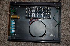
How about some progress pictures folks.
FWIW,
I'm laying out the chassis for my amps -decided to go with a pair of mono amps, using some old "junk" amp chassis I picked here and there.
As soon as the panels and heat sinks are drilled/tapped (and once I get some more power supply caps), I should be ready to assemble. 😎
C'mon, guys- Let's see your images!
-Chas
Attachments
dudaindc said:Chas - where did you get that power supply PCB?
It is looking good...
http://www.chipamp.com/orders.shtml
Scroll to the bottom, they are the Amplifier Power Supply PCB below the Aleph PCB. They are on sale with 20% off now. They make very neat and professional look power supply!!
pchw said:
http://www.chipamp.com/orders.shtml
Scroll to the bottom, they are the Amplifier Power Supply PCB below the Aleph PCB. They are on sale with 20% off now. They make very neat and professional look power supply!!
Thanks Fred.
That is not a bad price for such a nice board.
The link for the board is probably incorrect on the website as it leads to an XLS file (BOM) instead of a picture.

==================================
I found them... http://www.briangt.com/gallery/aleph-pcb 😀
do you have BOM for that pcb
also does the pcb support center tap transformer secondary
chas could you give us more Information about transformer
also does the pcb support center tap transformer secondary
chas could you give us more Information about transformer
Zooming in on the picture of the board it looks like it supports 4 MUR type diodes, so center tap transformers should work.
From memory, it also supports CCRC filtering - although with a Leach amp I'd just jumper out the R and use 3 parallel caps per rail.
From memory, it also supports CCRC filtering - although with a Leach amp I'd just jumper out the R and use 3 parallel caps per rail.
the Leach has pretty good PSRR and also Jen's version has the facility to power the voltage amp from a separate PSU, regulated or not.
The removal of R allows the whole capacitor bank to deliver transient current.
It may be that the loss of ripple attenuation is more than balanced by the improved peak current delivery.
If the resistor were to be replaced by 100turns of 0.6mm diameter enameled wire, the R value would be low and the ripple and interference suppression would be much improved. This may sound better than either of the other options.
But there's only one way to find out, try them.
AndrewT said:the Leach has pretty good PSRR and also Jen's version has the facility to power the voltage amp from a separate PSU, regulated or not.
The removal of R allows the whole capacitor bank to deliver transient current.
It may be that the loss of ripple attenuation is more than balanced by the improved peak current delivery.
If the resistor were to be replaced by 100turns of 0.6mm diameter enameled wire, the R value would be low and the ripple and interference suppression would be much improved. This may sound better than either of the other options.
I doubt the class A input circuitry needs to worry about peak current delivery since it is constant current. Thus, I would assume inclusion of the resistor would be MUCH more advantageous for filtering variations due to the current pulses in the output stage than any possible reduction in peak current delivery, if that is in fact a potential problem.
If the CRC is for the output stage, I do agree that an inductor may be a better choice; especially if it is placed away from the amp circuitry, as such an inductor may radiate into the circuitry. The front end would also be the most intolerant of such radiation.
Thinking about it a bit, I seem to remember that there are terminals intended to allow the connection of an inductor or resistor. Nice little boards, I think I'll go buy some.
pooge said:
I doubt the class A input circuitry needs to worry about peak current delivery since it is constant current. Thus, I would assume inclusion of the resistor would be MUCH more advantageous for filtering variations due to the current pulses in the output stage than any possible reduction in peak current delivery, if that is in fact a potential problem.
If the CRC is for the output stage, I do agree that an inductor may be a better choice; especially if it is placed away from the amp circuitry, as such an inductor may radiate into the circuitry. The front end would also be the most intolerant of such radiation.
It appears I was talking about the wrong boards. I thought it was the Leach amp boards being discussed. So I do not disagree with what Andrew said regarding the separate PS boards.
the ClassA voltage amplifier stage is not constant current.pooge said:I doubt the class A input circuitry needs to worry about peak current delivery since it is constant current.
AndrewT said:the ClassA voltage amplifier stage is not constant current.
Are you including the driver stage in this statement? Otherwise, I believe it is constant current.
Hi Andrew,AndrewT said:
If the resistor were to be replaced by 100turns of 0.6mm diameter enameled wire, ...
A stupid question, what is the equivalent of 0.6mm in terms of gauge, 14ga, 12ga?
thanks!!
http://en.wikipedia.org/wiki/American_wire_gauge says roughly 22 gauge. Perhaps Andrew mis-typed 1.6mm/14 gauge?
samoloko said:do you have BOM for that pcb
also does the pcb support center tap transformer secondary
chas could you give us more Information about transformer
Here is the BOM. It is an zipped excel spreadsheet.
Attachments
Thanks, Bob.BobEllis said:http://en.wikipedia.org/wiki/American_wire_gauge says roughly 22 gauge. Perhaps Andrew mis-typed 1.6mm/14 gauge?
I have some air coil from crossover. There might be a few 14ga. I am tempted to use those if possible - I suppose that a few turns is still better than a straight jumper 😀
Hi,
100T of 0.6mm wire on a 13.4mm bobbin wound as 10.6T/layer and 9.6layers will have an inductance of ~170uH and a resistance of ~0r37
100T of 0.6mm wire on a 13.4mm bobbin wound as 10.6T/layer and 9.6layers will have an inductance of ~170uH and a resistance of ~0r37
Andrew,
Please quote me a source for all that great information. It is something that may be quite useful in the future.
Thanks Tad
Please quote me a source for all that great information. It is something that may be quite useful in the future.
Thanks Tad
- Home
- Group Buys
- Jens Rasmussen Leach clone group buy