chas could you give us more Information about transformer
Sam,
The transformer was taken from an old 1970's receiver (in this case, a Pioneer). Some of these had nice, potted traf's that still work well today(no hum or stray fields). They may not have the 600+VA rating that many here seek, but they're gorgeous (IMHO), and not too expensive in my case.
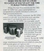
I prefer the SX-1250 model, if you can find a non-working one locally or on eBay, as it has dual 50vac secondary windings. This makes for a good 160+W(@8ohms) stereo amp. Just ask WJH!
Otherwise, you could try to find an SX1050(120W) as I have done.
Anyone else have pix?C'mon, guys- Let's see your images!
-Chas
p.s. Thanks, PCHW, for turning me on to BrianGT's power supply boards. They make the layout and wiring neat & easy!
Attachments
Speaking of savage old parts.
I totally forgot that I had a 170wpc Luxman receiver (R-117) that has blown output stages (all transistors are toasted as far as I could tell, preamp and tuner were still good) in the garage somewhere. It doesn't have the nice toroid, but the EI PT is massive. I shall dig it out and take some measurements to see I can use it!!
I totally forgot that I had a 170wpc Luxman receiver (R-117) that has blown output stages (all transistors are toasted as far as I could tell, preamp and tuner were still good) in the garage somewhere. It doesn't have the nice toroid, but the EI PT is massive. I shall dig it out and take some measurements to see I can use it!!
Marc,mpmarino said:Nuthin wrong with a good EI Fred - 😉
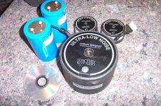
Here is my salvage toroid. Honestly, it came from a scrap guy.
That's why I'm building the amp... I needed a good amp for the traffo😀
Tell me how to dig out these kind of land mine, I will do the suicide dig

Nice find Marc.
At the risk of sounding like an ApexJr shill, the dual 45V Genesis transformers that Steve has are awfully nice. I haven't powered one up yet, but while rated at 600VA they are as big as my Avel 800VA transformer. (well, maybe 3/16" shorter).
At $29.95 they are a steal. Courtesy of USPS flat rate shipping, I got a pair and some caps delivered for $15. The only downside is you should go to 80V caps to be safe with nominal 63V rails.
Edit: OK, I admit it. I'm trying to get these sold so I won't buy the entire stock 😉
Here is my salvage toroid. Honestly, it came from a scrap guy.
Wow, Marc!
Tell me, did your "scrap guy" have any other(say ,"Krell") parts?

That's MY kind of scrap yard!! 😉
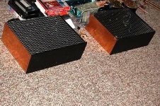
Attached is pic of progress on my two mono-block chassis.
I'm using 2mm copper plate(scraps)which acts both as side of enclosure and as heat spreader to join my two 6" wide heat sinks. The front(inner), back and bottom are 1/8" aluminum plate, adding some heat dissipation as well. Front panel is 1/4" brushed/anodized. All from "scrapped" enclosures. Top screen is expanded steel mesh from Home Despot (gotta let the heat out somehow, or we'll "cook" the caps)...
-Chas
Attachments
clm811 said:
Sam,
The transformer was taken from an old 1970's receiver (in this case, a Pioneer). Some of these had nice, potted traf's that still work well today(no hum or stray fields). They may not have the 600+VA rating that many here seek, but they're gorgeous (IMHO), and not too expensive in my case.
I prefer the SX-1250 model, if you can find a non-working one locally or on eBay, as it has dual 50vac secondary windings. This makes for a good 160+W(@8ohms) stereo amp. Just ask WJH!
Otherwise, you could try to find an SX1050(120W) as I have done.
Anyone else have pix?
-Chas
p.s. Thanks, PCHW, for turning me on to BrianGT's power supply boards. They make the layout and wiring neat & easy!
How sad, those sx-1xxx receivers are major collector items, even the non-working ones go high on ebay for repair parts. I decided to go with toroids from audio express.
How sad, those sx-1xxx receivers are major collector items. . I decided to go with toroids from audio express.
Understood; However, I had trouble with hum from an unshielded toroid in one of my current amplifiers.
I like idea of using the steel-encased, potted traf to avoid such a problem. Like Marc, I've looked to Levinson and Krell units to see what is preferred at the "top end". Fortunately I found these excellent trafs. at very fair prices on eBay.
Cheers,
-Chas
Can't tell from the photos...
Anybody using TO220 type heatsinks on the driver transistors in this amp project? If so how big should they be?
-Joe
Anybody using TO220 type heatsinks on the driver transistors in this amp project? If so how big should they be?
-Joe
If you don't want to use the big holes Jens provided to attach the drivers to the main sinks, you can use something like Mouser P/N 532-504102B00.
Early versions of the board mounted the drivers and heat sinks on top of the board. There was a potential issue with interference between the sinks and the snap in caps. This version solves that issue by allowing the devices to mount to the main heat sink.
Early versions of the board mounted the drivers and heat sinks on top of the board. There was a potential issue with interference between the sinks and the snap in caps. This version solves that issue by allowing the devices to mount to the main heat sink.
...you can use something like Mouser P/N 532-504102B00.
I looked up the Mouser part, and the dimensions are listed as 19.812 mm L x 17.78 mm W x 21.59 mm H
The reason ask is because I already have some TO220 'sinks measuring 18mm x 10mm x 20mm.
Would these be large enough for the drivers in a 120-150W extended Leach amp?
-Joe
That sounds like the same basic part. The difference could be tolerances in part and your measurements.
I've had my Leach amps running for almost 10 years at 60V rails with similar sinks with fins only about 12 mm high. Yours should be fine. Be careful that you don't short the sink to ground or the snap in cap case.
I've had my Leach amps running for almost 10 years at 60V rails with similar sinks with fins only about 12 mm high. Yours should be fine. Be careful that you don't short the sink to ground or the snap in cap case.
Power supply question
Guys,
Granted, Dr. Leach has recommended 12,000uf for the main PS rails in his writings, but I'm guessing that a few here have experimented with this(more or less)...
In a class AB amp to be used with a (sub)woofer system, what do you find to be the minimum amount of PS filter capacitance that will provide good bass power and control (assuming the user has already optimized the woofer design and placement)?
TIA,
-Chas
Hi,
the PSU smoothing capacitance is linked to the passband of the amplifier.
PSU RC >=sqrt(2) * NFB RC
NFB RC >=sqrt(2) * Input high pass RC.
If the input RC =80mS (1u5 & 51k), then NFB RC >=113mS. 1u5F & 53k
If the NFB RC =113mS (150uF & 750r), then the PSU RC >=160mS.
For 8ohm speakers C must be >=+-20mF/ch.
For 4ohm speakers C must be >=+-40mF/ch.
For very high power amplifiers, a second rule becomes applicable.
>=2mF/Apk of output current, to reduce cap ripple to an (arguably) acceptable level.
Chas,
The depth of your money stack also comes into play here. Good quality 75 plus volt capacitors are not cheap. I chose to use 75000 uf per channel and the results are good. Using a film cap to parallel the electros has favorable results. If the music continues to play for about a minute or more after you turn off your amp you can bet there is adequate reserves for most musical transients even as sub woofer duty.
Tad
Tad,
the results are good, or outstanding? I had planned on 22,000 per 70V rail.
I just can't quite figure out AndrewT's formula and how it relates to the rail capacitance (I know, go back and read the stuff.. 🙄 ) I popped for the 1000VA tranny to help mitigate my other poor design choices 😀
the results are good, or outstanding? I had planned on 22,000 per 70V rail.
I just can't quite figure out AndrewT's formula and how it relates to the rail capacitance (I know, go back and read the stuff.. 🙄 ) I popped for the 1000VA tranny to help mitigate my other poor design choices 😀
it's not mine. I simply adopted it when I discovered it worked well on all my amps.rob3262 said:I just can't quite figure out AndrewT's formula and how it relates to the rail capacitance
Pick your LF roll off frequency (F-3db).
Select the input filter components to achieve that frequency.
Then use the two formulae to determine first the NFB DC blocking cap value and secondly determine the smoothing capacitance to suit your speaker impedance.
Rob,
There is a lot of exceptional information that Andrew provides to us that I do not understand. But if not for his and other devoted members input I would be farther in the dark than I am. When I first started reading posts here I did not know the difference between a mosfet and bjt transistor.
Slowing absorbing little breadcrumbs along the way may one day lead to construction of a truly monumental amplifier or some other using item. I only wish I had started 45 years ago
I think we have a truly great pcb layout here, thanks to Jens and others, from which we can construct and amp the quality of which most of us could not afford at retail. I have read nothing but praise for Dr. Leach's protege.
Thanks Tad
- Home
- Group Buys
- Jens Rasmussen Leach clone group buy