Hi Bob,
Do you have a better picture of how is the thermal diode mounted on the heasink? There's a picture of this thermal diode mounted at the bottom of the main pcb to the heasink at Delta-Audio website but it's not clear to me. I'm not sure if the diodes should be facing the heatsink laying flat or not.
Thanks,
Fred
I wonder if it would be possible to substitute 4 thermal trac output devices in this amp and wire the diode string to the pads where the 4 normal diodes go? Any ideas on this. Tad
This question is hypothetical for all you new constructors. O.K.
Tad
Fredlock, The diodes you are referring too are soldered directly to the small pad provided as part of the pcb. Standard diodes or smd types both work. You cut this piece off with a saw, dremel or what ever. Make sure the leads of the diodes do NOT PROTRUDE through the board and touch the heatsink. Then you screw this small board down to the heatsink all of which is mounted under the main board. There are two windows for the screwdriver and screws to be accessed. The copper in the diode board provides good thermal delivery for the diodes to track with the heatsink temperature. You then run 2 wires from the small board pads to the pads on the main board. Everything is well labeled on the silkscreen printing. If you layout all of the areas you are going to drill and tap with clean empty board and make your connection wire long enough it is not too terrible difficult.
It would be relatively easy to hard wire the diode pins together to form the Vbe multiplier temperature compensation.
If Diodes alone are used then 5 seem to compensate for the four Vbe variations of the driver and output stage.
When Leaches diode compensation is used 3 diodes seems to be too little (undercompensated) and four is clearly too much (over compensated).
It appears we have a choice,
use Leach with three diodes hard wired into the Vbe
or
use 5diodes without the Vbe multiplier.
Bob, Does your earlier post suggest you are actually working on a BOM for the super guy. I have been wondering of late if most objectives are not acheived with the current board. If you use Nelson's kiss principal the super guy is like one or two devices past complex. I wonder if oscillation is going to be an issue with 16 op's. That monster though fun to build is not going to come cheap. What is the standard phrase -- get ur done. More toys just in time for Christmas. Tad😀
Tad,
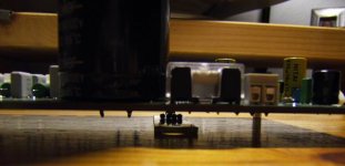
Thanks for your reply. What I'm trying to understand is, if the thermal diodes should be facing the heatsink or not. But based on this picture attached, seems like the thermal diode board is facing upward. Would it be better to be facing down for a better thermal sensing? On the original leach amp, they used to stick those diodes in the heatsink. Just wondering? 😕
Thanks for your reply. What I'm trying to understand is, if the thermal diodes should be facing the heatsink or not. But based on this picture attached, seems like the thermal diode board is facing upward. Would it be better to be facing down for a better thermal sensing? On the original leach amp, they used to stick those diodes in the heatsink. Just wondering? 😕
Attachments
Fred,
If you read Professor Leach's page closely you'll see that three diodes was a better amount of compensation than 4 (slightly overcompensated), but 4 was chosen so that the leads would come from the same side of the heat sink.
There have been hundreds of these boards sold and I haven't heard of anyone having thermal runaway issues. You should be safe mounting as pictured. (just ensure that the diode leads are clipped short enough that you don't have electrical contact between them and the sink.)
AndrewT - do I remember you doing some testing to verify correct compensation?
Frelock, Read what Jens has to say about this on his website. Delta-Audio.com. He makes some reference to this area. Tad
Hi All,
Thanks to Tryonziess in advance. I am starting to collect all components for these AMP. I am so badly have it in earlier 😀
Come up the question if I operate this AMP as Class A mode around 40W~50W per channel.
1) Then how large the rectifier's CAP should be used for single channel +/- 56VDC (unloaded) ?
2) Should I deploy a regulator in this case ?
CK
1. For 50W class A into 8R you'll need 2.5A out - bias at 1.25A = Lots of heat sink and/or fans. Double that for 4 ohm loads. I'd shoot for 50-100,000 uf per rail. This means lots of inrush current, so you'll need some form of inrush limiter.
The one shot inrush current drives your rectifier choices. I'd shoot for a 30A or more canned bridge firmly mounted to the case, or if you are using exotic discretes, at least 20A rating and be sure to heat sink them. You can predict the inrush current using psu designer. I'd also go 300+VA for the transformer.
2. Regulating the front end supply would be good, both sonically and to allow you to operate the front end at 45+ volts to avoid having to mod the cascode while lowering the output rails to reduce dissipation. With 34V rails (25V transformer) you can get 50W+ out, giving you "only" 87.5W per channel idle dissipation.
Watch the safe operating area of your output devices - calculate the junction temperatures and derate appropriately. Consider mosfets which will be more thermally stable at the elevated bias.
The Pass A75 articles at www.passdiy.com are a good read, and will explain the thermal considerations a bit better than I can. Thermal considerations will be your biggest obstacle to 50W class A operation.
AndrewT said:When Leach's diode compensation is used 3 diodes seems to be too little (undercompensated) and four is clearly too much (over compensated).
Bob, how do I make it any clearer?BobEllis said:AndrewT - do I remember you doing some testing to verify correct compensation?
Thanks Andrew. I wasn't sure if I remembered you testing this amp or another for thermal compensation.
There are stil quite a few folks who have not yet sent me an email with their name, address, no. boards, email address, method of payment.
I would like to begin invoiceing this week. Also, If you are on the wiki page I am going to assume you are interested in the pcb's. There are 10 boards left. Tad
I would like to begin invoiceing this week. Also, If you are on the wiki page I am going to assume you are interested in the pcb's. There are 10 boards left. Tad
schematic
seems I have two different schematic revisions, 5.6.10 & 9.05.10
The only difference I find is signal ground callout.
Same difference?
seems I have two different schematic revisions, 5.6.10 & 9.05.10
The only difference I find is signal ground callout.
Same difference?
Re: schematic
In short yes, there shound be no difference to the two sheets, but I updated the layout for the 9.05.10 with BC types transistors in stead of the MPSA style ones in the original design.
\\\Jens
rob3262 said:seems I have two different schematic revisions, 5.6.10 & 9.05.10
The only difference I find is signal ground callout.
Same difference?
In short yes, there shound be no difference to the two sheets, but I updated the layout for the 9.05.10 with BC types transistors in stead of the MPSA style ones in the original design.
\\\Jens
I just sniped a PS Audio 200C on eBay for parts(massive traf and caps, plus 4 massive heatsinks and a large cabinet).
I'm thinking of using it as the basis for my 10 transistor Leach clone, running on 75v rails...
Any comments/suggestions?
-chas
ps: forgive the hasty "morph", sloppily done in mspaint
I'm thinking of using it as the basis for my 10 transistor Leach clone, running on 75v rails...
Any comments/suggestions?
-chas
ps: forgive the hasty "morph", sloppily done in mspaint
Attachments
Duh, you already know, otherwise you wouldn't have bought the 200C.
Awesome chassis for a conversion, especially the copper brackets and heatsinks.
Very similar build and equally heavy as big buckster stereo amps such as a 1st gen. Electrocompaniet AW250.
I'd keep the copper iiwy, you can close TO-3 pattern holes again with pressed-in copper inserts.
Afair, the transformer is a 1K specimen.
Robert Odell may not like his baby being hacked.
You should show the Leach droooolers a piccy of the 200C's front plate, also a beaut for an amp conversion mock-up job.
Why hack up that monster. Restore it. You can find something less extravagant to hack. Nice toy. Tad
Wake up!!!
Some of you folks on the wiki page have still not sent me confirmation e-mails. I need these to send out invoices and mail you your stuff. Send me your name, address, email, number of boards and method of payment.
I have just finished sending out invoices for all of those who sent me the above info.
Another little note. Pay close attention to the PCM widths on the film caps for this board. Some of them can be difficult to source in the better grades. And remember what Bob said about the fuse holders. My 2 cents.
Tad
Paypal is merciless!!! I can not for the life of me figure out what kind of system -- if any -- these folks use to figure interest. Sometimes it is nothing and other times it is 3.5 to 4 percent. Go figure. I guess that is how you become a multi-billionaire. My two cents again.
Other than that things are moving along real nice with the group buy. I just scrapped my two frontend transformers because I misfigured the voltage output. Running both secondaries in series gives me 38 volts to ground not the 75-80 I need. I will try something else. I actually know better just not paying attention.
Tad
- Home
- Group Buys
- Jens Rasmussen Leach clone group buy