Re: -or...
Using the copper angles in the power amp as the rails means that the output devices and the power supply caps are mounted directly to them.
No insulators under the output devices and feeding them straight from the copper rails has both a merit for the supply of power and a thermal advantage.
Judging from the picture, it seems like all it takes to mount the Leach board is moving the outer heatsinks a bit to the center, closing the TO-3 holes and re-mounting the copper with a silicon insulator sheet.
I'd be prudent to ditch something as pretty, the average DIY-er will not be able to manufacture copper angles identical to the ones in the 200C.
clm811 said:not using the copper plus/minus rails
Using the copper angles in the power amp as the rails means that the output devices and the power supply caps are mounted directly to them.
No insulators under the output devices and feeding them straight from the copper rails has both a merit for the supply of power and a thermal advantage.
Judging from the picture, it seems like all it takes to mount the Leach board is moving the outer heatsinks a bit to the center, closing the TO-3 holes and re-mounting the copper with a silicon insulator sheet.
I'd be prudent to ditch something as pretty, the average DIY-er will not be able to manufacture copper angles identical to the ones in the 200C.
Using the copper angles in the power amp...
...I'd be prudent to ditch something as pretty, the average DIY-er will not be able to manufacture copper angles identical to the ones in the 200C.
These huge copper angles connect from the PSU cap +/- terminals to the transistor cases and then there are other copper angles that connect to the spkr output terminals- what about those...?
all it takes to mount the Leach board is moving the outer heatsinks a bit to the center... and re-mounting the copper with a silicon insulator sheet.
Closing the T03 holes- how would you do this(I'm guessing inserting a similar diameter copper rod, soldering in place, then trimming)? Would you say to avoid using T03's (with their required extra lead wires)?
"Remounting the copper (to the heatsink?)with a silicon insulator sheet" - does this truly preserve the thermal advantage of the copper, as opposed to going directly to the heat sinks, as Andrew T. suggested? Also, would heat sink compound be contraindicated here?
TIA
-chas
AndrewT said:5pair of MJL4302/4281 (To264 230W) is a superb output stage and will work very well on a +-75Vdc supply.
Are you building 2channels? i.e. 10off each device. Buy 12off each and select the 5 closest in the lower group and 5 closest in the upper group for the NPNs. Repeat for the PNPs. This should give adequate matching of the BJTs.
Andrew
when matching the output transistors - 5 NPN in lower group goes to one channel and 5 NPN In upper - to the other, correct
also the the lower 5 PNP - respectively to the channel where are the lower NPN, correct
I will use trafo with 2 x 28.4 VAC which will give about 40 vdc rails
I would like to know what value of R3 and R22 to use since I will not use trafo with 2 x 40 VAC
are there any other values to change
Hi,
a 5pair output stage on +-40Vdc seems such a waste of resources.
Unless you plan to go for a high bias ClassAB or use very low Re to increase the optimum ClassAB bias (Vre=20mV) eg. Re=0r1 would dissipate 80W quiescent on +-40Vdc and give 16W of ClassA output before changing to ClassB for the remaining 60W of output.
Sam -
At 40V you won't have enough voltage for the 40V zener stack that is the reference for the cascode. This changes the current in R3 and R22.
I'd use a combination of 20 V and 9.1V in the zener stack and change the equation to R(K)= (V-29.1)/8.2
I second AndrewT's comments. Spring for a higher voltage transformer and enjoy the headroom.
or delete one Zener from each stack.BobEllis said:Sam -
At 40V you won't have enough voltage for the 40V zener stack that is the reference for the cascode. This changes the current in R3 and R22.
I'd use a combination of 20 V and 9.1V in the zener stack and change the equation to R(K)= (V-29.1)/8.2
I second AndrewT's comments. Spring for a higher voltage transformer and enjoy the headroom.
The heatsinks can even run live, personally i'm not too keen of that.
I built a few power amps with MOSFET TO-220 output devices, mounted with just thermal goop on an insulated L-shape profile.
Mounting them with mica insulators straight to the heatsink would have required fan forced cooling of the heatsinks.
If the contact surface between the bracket and the heatsink is sufficiently large and smooth enough, it saves a lot of thermal resistance.
The ground return in the 200C is a copper bar as well, the hardware volume in this early 80s power amp is remarkable, in particular considering it's msrp.
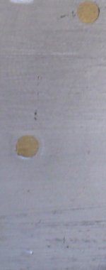
Tight fitting copper rod inserts, flat end surfaces, just a weeny bit longer than the thickness of the copper angle.
Brass works too, though much harder to transform than copper.
Best would be to press them in, but that requires access to pro machinery.
At home you just put the copper angle between two lengths of large dimension solid square steel and flatten the inserts with a hammer, finish with a dremel or a hand-file job.
Example picture=>
I built a few power amps with MOSFET TO-220 output devices, mounted with just thermal goop on an insulated L-shape profile.
Mounting them with mica insulators straight to the heatsink would have required fan forced cooling of the heatsinks.
If the contact surface between the bracket and the heatsink is sufficiently large and smooth enough, it saves a lot of thermal resistance.
The ground return in the 200C is a copper bar as well, the hardware volume in this early 80s power amp is remarkable, in particular considering it's msrp.
Tight fitting copper rod inserts, flat end surfaces, just a weeny bit longer than the thickness of the copper angle.
Brass works too, though much harder to transform than copper.
Best would be to press them in, but that requires access to pro machinery.
At home you just put the copper angle between two lengths of large dimension solid square steel and flatten the inserts with a hammer, finish with a dremel or a hand-file job.
Example picture=>
Attachments
and then hone "flat" if any semi passes over these "rivets".jacco vermeulen said:Tight fitting copper rod inserts, flat end surfaces, just a weeny bit longer than the thickness of the copper angle.
Brass works too, though much harder to transform than copper.
Best would be to press them in, but that requires access to pro machinery.
At home you just put the copper angle between two lengths of large dimension solid square steel and flatten the inserts with a hammer, finish with a dremel or a hand-file job.
thx Andrew and Bob
at moment I only have 2 x 150 W Avel toroids
maybe I have to look for a new toroid
at moment I only have 2 x 150 W Avel toroids
maybe I have to look for a new toroid
A boaty would "rivet" with just two hammers. 
I still need to schedule a couch session for all the hours my dad forced me to hold the bottom sledgehammer.
"Honing" can be done with a sheet of sandpaper on a mirror, the traditional way for cylinder heads.
I still need to schedule a couch session for all the hours my dad forced me to hold the bottom sledgehammer.
"Honing" can be done with a sheet of sandpaper on a mirror, the traditional way for cylinder heads.
tryonziess said:Paypal is merciless!!! I can not for the life of me figure out what kind of system -- if any -- these folks use to figure interest. Sometimes it is nothing and other times it is 3.5 to 4 percent. Go figure. I guess that is how you become a multi-billionaire. My two cents again.
...
Tad
Tad
This is what I use and so far it has been 100% correct.
PAYPAL FEE CALCULATOR
Cheers!
To all,
I am receiving numerous inquiries for pcb's. All of the current supply in this group buy are spoken for. Please if you are on the wiki page confirm your order and I will send you an invoice. I wish to get boards to those who want them.
One small question to the knowledgeable. What are the differential current limiting diodes on the Jens board rated for in terms of voltage. Dr. Leach never intended for the Low TIM amp to be driven with 70 volt rails. His design has 2 - 20 volt zeners in series. Was this diode design changed to accomadate the increased rail voltages or does it need to be? I am not learned enough to answer this question.
Tad
The Zeners set the tail current resistor voltage. It is in effect a CCS for the LTP.
40V does not need to be changed for any PSU above +-50Vdc.
But the feed resistor to the Zener must be scaled to suit the PSU voltage. Leach gives the formula and I think Jens also gave assistance here.
If PSU <50Vdc then I suggest the Zener voltage is reduced to either 30 V or even as low as 20V.
The reasons given by Leach for choosing two sets of series diodes was to help eliminate the effect of the wide tolerance of Zener voltages. He argued it was much easier to get a pair of near 40V voltages from 4 diodes than trying to find 39V Zeners that matched. I agree, it was very easy to select twins to give matching voltages on the tail resistors.
Tad,
The zeners provide a voltage reference for the front end cascodes. They are not current limiting. Notice the super amp uses the same values.
R3 and R22 change with rail voltage to limit the zener current to about 5 mA. Notice the equation for R3 and R22 is rails minus 40 - the zener stack voltage. The 8.2 denominator represents the current in the zener plus the current in three legs of the differential.
If you must , err on the low side for R3 and R22, which will increase the current in the zener stack. You want enough to regulate properly, 5 mA is sound, and 10 mA in the zener won't hurt anything. Just watch the dissipation in R2 and R22 = (V-40)^2/R
I am Interested to know how Important are polar caps C21, C27 and all the C22 - C26 and C28 - C32
are these essential or just a extra
are these essential or just a extra
Thanks, Jacco!
Looks like that's how the 200C was configured. They're internal heat sinks, so with the cover on there's no hazard( but I'd better be careful when working on this sucker, or -ZAP!) 😱
The copper is highly polished, and it looks like they are in intimate contact with the heatsink.
The heatsinks can even run live, personally i'm not too keen of that.
Looks like that's how the 200C was configured. They're internal heat sinks, so with the cover on there's no hazard( but I'd better be careful when working on this sucker, or -ZAP!) 😱
If the contact surface between the bracket and the heatsink is sufficiently large and smooth enough, it saves a lot of thermal resistance.
The copper is highly polished, and it looks like they are in intimate contact with the heatsink.
...Tight fitting copper rod inserts, flat end surfaces, just a weeny bit longer...put the copper angle between two lengths of large dimension solid square steel and flatten the inserts with a hammer QUOTE]
Ok I suspected that, just like my Dad used to hand-make his stuff on an anvil (Grandpa was a blacksmith)!
-chas
samoloko said:I am Interested to know how Important are polar caps C21, C27 and all the C22 - C26 and C28 - C32
are these essential or just a extra
C21 and 27 could be eliminated or could be the only cap needed after the bridge. Jens intended them for local decoupling with a large cap bank in the PSU. If you use enough capacitance you could have a bridge feeding each channel giving some decoupling between channels sharing a common transformer.
The rest that you mentioned are optional. They provide a little decoupling right at each output device, but are not absolutely necessary. Will they have a sonic benefit? Possibly. Mouser has appropriate caps for $.25 each so I'm springing for them.
Bob and Andrew,
It is nice to be able to draw in the depth of knowledge. Thanks
I was rereading - 50th time -- the information on Leach's website and came across the above. That is where the question arose.
Tad
It is nice to be able to draw in the depth of knowledge. Thanks
I was rereading - 50th time -- the information on Leach's website and came across the above. That is where the question arose.
Tad
BobEllis said:
C21 and 27 could be eliminated or could be the only cap needed after the bridge. Jens intended them for local decoupling with a large cap bank in the PSU. If you use enough capacitance you could have a bridge feeding each channel giving some decoupling between channels sharing a common transformer.
Hi Bob
would you please clear - If I got 1 pcs of transformer and 1 pcs of bridge feeding two channels - then there Is a need of C21 , C27 (all that additional caps) no mater what values are filter caps after bridge
what values do you recommend for filter caps after bridge
what have to be the feeding power supply from regulator supply board for the front ends
- Home
- Group Buys
- Jens Rasmussen Leach clone group buy