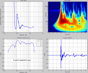
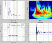
Not so different from what I'm using at the moment.
Frode
Heja Frode,
Interesting! How is your midbass hornreflex "tuned"? Also is it tractrix expansion? Your corner placement should work.
Heja Frode,
Interesting! How is your midbass hornreflex "tuned"? Also is it tractrix expansion? Your corner placement should work.
They are around 140L and tuned at ~35Hz. The horn is a modified Oris 150.
Frode
Hello Frode,
Please, could you send me the impulse response so I can use my own software to analyze the signal and erive a wavelets transform grapha.
jean-michel.le_cleachXmines-paristech.fr
(replacing the X by the arobase)
Eventually, could you perfom another measurement between 1 and 2 meters from the horn.
Best regards from Paris, France
Jean-Michel Le Cléac'h
I use the Iwata 300 with the BMS 4592ND. If anyone is interested in a closer look, I can send them the impulse response as a .pcm file.
Please, could you send me the impulse response so I can use my own software to analyze the signal and erive a wavelets transform grapha.
jean-michel.le_cleachXmines-paristech.fr
(replacing the X by the arobase)
Eventually, could you perfom another measurement between 1 and 2 meters from the horn.
Best regards from Paris, France
Jean-Michel Le Cléac'h
Frode. That last graph is very nice, thanks! Looking forward to seeing what a closer measurement and J-M's analysis will reveal. For the moment it looks darn good.
Hello,
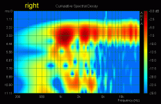
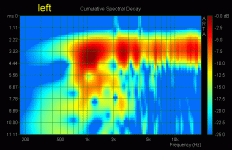
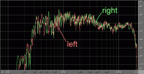
In a first step I used ARTA and Adobe Audition,to analyse the Impulse Response of the Iwata300 loading a BLMS driver 4592Nd (mid+ tweeter coaxial)sent to me by Frode.
You can find in attached file;
- a magnification of the impulse responses showing that the tweeter is inverted.
- the constant decay graphs
- the frequency response curves (given by Adobe Audition)
I'll comment about thos graphs latter.
Bestregards from Paris, France
Jean-Michel Le Cléac'h
Attachments
Last edited:
Hello,
I used my Matlab routine in order to analyse the Impulse response of the Iwata300 + BMS4592Nd measured by Frode in his listening room :
http://i32.photobucket.com/albums/d40/frodeh/Audio/polen/P1010580.jpg
You can find in attached file a screen copy of the results.
The frequency response is obtained after applying to the pulse response, a windowing limited to 2.8ms after the pulse arrival. This explains the lack of the lowest frequency and the smooth curve at low frequency (there is no conventional smoothing applied in that FR). Despite the small width of the window we can see below that below 2500Hz a noticeable comb effect pollute the mesurement. I think this is due to the side wall of the room very near of the mouth of the Iwata300 producing a reflection visible at 0.75ms on the impulse response.
The response curve between 5kHz and 20kHz is several dB less than the response between 900Hz and 4kHz. This is because the BMS is a coaxial driver with a central tweeter part having its own filter. Eventually a passive equalizer may be used on the mid part of the driver to equalize the levels.
Considering the group delay curve we can see that the equivalent GD is larger than 10 centimeters below 650Hz. If I had to use the Iwata300, I'll used it above 650Hz. (Notice the secondary peak of GD between 900Hz and 16800Hz which is probaby due to interference between the direct wave and the reflection on the side wall previously mentionned.
On the magnification of the impulse response attached to my previous message, we could see that the tweeter is connected in an opposite polarity versus the medium. This choice was probably perfomed in order to obtain a more constant frequency response curve but at the expense of the shapeof the lmpulse response. Some work on the crossover used between the LF and HF parts of the coaxial driver could ameliorate the impulse response. The delay introduced by the crossover can be seen on the arrival of the pulse around 5.6kHz on the spectrogram.
The structure of the coaxial driver used is at the origin of some diffraction (and HOMs creation) occuring. We have to consider that the radiation of the LF frequencies at the throat is performed by an annular surface, when the horn would prefer a full 2inches disk radiation. I would like to study measurements performed on the Iwata300 using a non coaxial comprression driver.
Best regards from Paris, France
Jean-Michel Le Cléac'h
Attachments
Last edited:
I doubt it's inversion of polarity, but rather some problem between the driver and horn. I've seen this in some simulations, and change in horn profile solves this.
Hello Soongsc
One reason could be also some ringing between 15kHz and 18kHz as seen in the datasheet.
http://www.bd-design.nl/contents/en-us/4592ND.pdf
But the driver is coaxial and its original crossover seems to be suboptimal. This is why Bert Dopenberg used to modify the crossover between mid and tweeter in the BMS4592Nd used on an Oris horn.
See:
BMS
Best regards from Paris,
Jean-Michel Le Cléac'h
I doubt it's inversion of polarity, but rather some problem between the driver and horn. I've seen this in some simulations, and change in horn profile solves this.
Last edited:
I would like to study measurements performed on the Iwata300 using a non coaxial comprression driver.
hello jean michel,
i doubt that mesureament could be helpful, i am not good with that. But if you ve got few minutes, i have à pair of the iwata with tad 4001 few meters away from the melaudia's meeting point.
Best regards
anthony
Hello Anthony,
You have a private message.
best regards from Paris, France
Jean-Michel Le Cléac'h
You have a private message.
best regards from Paris, France
Jean-Michel Le Cléac'h
Hello,
I used my Matlab routine in order to analyse the Impulse response of the Iwata300 + BMS4592Nd measured by Frode in his listening room :
Thanks for further analysis - all in all it looks more reasonable like this 🙂
But the driver is coaxial and its original crossover seems to be suboptimal. This is why Bert Dopenberg used to modify the crossover between mid and tweeter in the BMS4592Nd used on an Oris horn.
I've seen some posts too where folks have used their own XO for the coax with considerable benefit - also applying some precise delay for correction - but sadly I could not find again at quick search.
Michael
Last edited:
I agree with Jean-Michel that the small coaxial HF driver of the BMS is one of the reasons for the uneven time and frequency responses. The gap between the small HF driver and the significantly larger entrance of the horn is going to cause reflections and an uneven air-load over the working range of the HF driver - in effect, it's like loosely placing a small-format driver directly against the entrance of a large-format horn with no coupler. Yes, it can be equalized, but can the reflections be removed through equalization?
At first glance, it would seem like the coaxial principle "ought" to work, but actually, the frequency range where both drivers are working together (and in phase with each other) is actually rather narrow. Over most of the frequency range, it's either the MF or HF driver, but not both. And only the MF driver is the same size as the entrance to the horn, while the HF driver is much smaller, which is certain to cause reflections.
A Tannoy Dual Concentric is rather different, with the LF cone acting as a small horn for the compression-driver tweeter. Of course, if the Dual Concentric is placed in a front horn, the same problem as the BMS re-appears.
Last edited:
i have had and used the BMS 4592 in Bert's Orphean horn for some time. What most bothered me was beaming of the treble. It simply did not sound right. A dedicated tweeter with wide dispersion open things up, and sounds better to me.
At first glance, it would seem like the coaxial principle "ought" to work, but actually, the frequency range where both drivers are working together (and in phase with each other) is actually rather narrow. Over most of the frequency range, it's either the MF or HF driver, but not both. And only the MF driver is the same size as the entrance to the horn, while the HF driver is much smaller, which is certain to cause reflections.
Hmm ... I think I skipped over the implications of phase-angle differences between the inner HF diaphragm and the outer MF diaphragm a little too quickly. Over the frequency range where one driver is 3 dB down or less (which is a function of the sharpness of the crossover), this phase-angle difference will deform the shape of the wavefront that enters the horn.
If the phase difference could be kept to 30 degrees or less (which would take extremely precise crossover control), the wavefront deformation would not be too significant, but if it were in excess of 90 degrees, the wavefront entering the horn would be very strange indeed. The horn can't magically "unscramble" the wavefront; if it is deformed when it enters, it will only get worse as it expands through the horn, leading to chaotic results as it exits the horn and enters the room.
Since the acoustic phase angle is not easy to control in the crossover region (being a vector sum of the electrical and acoustic terms), that would argue for a steep-slope crossover to minimize the out-of-control region. The alternative would be a carefully modeling of the acoustic phase response for both HF and MF drivers (in the crossover region) and using the function as part of the crossover design process, aiming for less than 30 degrees of phase difference between the drivers.
It's common practice in direct-radiator systems to use the acoustical phase response as part of the overall crossover design, but it is much harder in systems where the acoustical phase is not a smooth function - compression drivers being a good example.
Last edited:
Bodzio UE
The new Bodzio Ultimate Equalizer program might be the magic set up for crossover and phase linearization of these coax drivers.
.
.
The new Bodzio Ultimate Equalizer program might be the magic set up for crossover and phase linearization of these coax drivers.
.
.
Hmm ... I think I skipped over the implications of phase-angle differences between the inner HF diaphragm and the outer MF diaphragm a little too quickly. Over the frequency range where one driver is 3 dB down or less (which is a function of the sharpness of the crossover), this phase-angle difference will deform the shape of the wavefront that enters the horn.
If the phase difference could be kept to 30 degrees or less (which would take extremely precise crossover control), the wavefront deformation would not be too significant, but if it were in excess of 90 degrees, the wavefront entering the horn would be very strange indeed. The horn can't magically "unscramble" the wavefront; if it is deformed when it enters, it will only get worse as it expands through the horn, leading to chaotic results as it exits the horn and enters the room.
Since the acoustic phase angle is not easy to control in the crossover region (being a vector sum of the electrical and acoustic terms), that would argue for a steep-slope crossover to minimize the out-of-control region. The alternative would be a carefully modeling of the acoustic phase response for both HF and MF drivers (in the crossover region) and using the function as part of the crossover design process, aiming for less than 30 degrees of phase difference between the drivers.
It's common practice in direct-radiator systems to use the acoustical phase response as part of the overall crossover design, but it is much harder in systems where the acoustical phase is not a smooth function - compression drivers being a good example.
If it can do inverse correction of time response for each driver, yes indeed, that would be the way to go for the BMS coaxial driver. I'd be a bit concerned the time response might change with each change in microphone position, leading to some difficult decisions for the crossover design (which emission angle has the "best" time response).
- Home
- Loudspeakers
- Multi-Way
- Jean Michel on LeCleac'h horns
