I was actually thinking of removing the onboard reg and cap multiplier and supply with a Jung regulator.
Do
Did you make the pcb of the jung regualtor?
If so, I would like to buy some.
If LM317 / 337 regulator cap multiplier PSU Is used and approved with years It Is well done and LM317 337 are not so bad
I wonder If I can use same tip - add a cap multiplier to LM317 / 337 only based dac PSU
I wonder If I can use same tip - add a cap multiplier to LM317 / 337 only based dac PSU
Did you make the pcb of the jung regualtor?
If so, I would like to buy some.
Didn't have time to go through that yet... Been busy with other projects and my friend who will be making the layout has not been available. Will keep everyone updated when/if completed.
Do
Didn't have time to go through that yet... Been busy with other projects and my friend who will be making the layout has not been available. Will keep everyone updated when/if completed.
Do
In case your friend wants to share the layout, I'm willing to do a small run for personal/friends use.
Chris, where would you take the AC measurement for the impedance change? At the amplifier's line input/R2R shunt ladder output?
The theory (to be tested) is that the volume control (assumed to be at the front of the signal chain) and the active electronics' input (assumed to be next in the signal chain) form a voltage divider. If both channels' impedances are the same, they'll have the same voltage at the junction of volume control and active electronics for both channels.
All good fortune,
Chris
What type of signal would you pass into the amp to test? Regular music or test signal of some sort?
Thanks
Do
In case your friend wants to share the layout, I'm willing to do a small run for personal/friends use.
I have no problem sharing the layout with everyone once it is completed
Do
Better News
JC-80 apparently safe; house still standing yesterday. 47k acres scorched and fire still only 10% contained. 1000 firefighters on the ground with 100 engines today. LOTS of winged water tanks flying around.
InciWeb the Incident Information System: High Park Fire
We will prollyNot be working much on audio for a while so please work out all the issues so ole Wolfsin can build clean JC-80 next Winter 😀
1Khz sine wave as signal any good for testing?
Nowhere near enough 😉
100hz, 1khz and 20khz thd + 19-20khz IMD tests will do good 🙂
It just depends: If you have a good 1K source and a way of seeing individual harmonics, you can do well enough. I personally use a 5K source for most of my testing.
This is not true for ALL circuitry, but for the JC-80, this is OK.
This is not true for ALL circuitry, but for the JC-80, this is OK.
1Khz sine wave as signal any good for testing?
Yes of course.
Chris
Many thanks John.
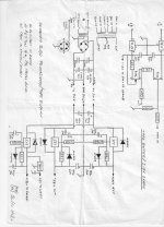
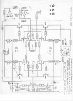
BTW excellent hand writing and technical drawings.
Best regards,
Patrick
BTW excellent hand writing and technical drawings.
Best regards,
Patrick
Last edited:
Would you care to comment on the use of VN01 / VP02, compared to the well-known Toshiba or Hitachi TO220 devices, or even TO92 devices ?
Regards,
Patrick
Regards,
Patrick
Last edited:
- Home
- Source & Line
- Analog Line Level
- JC-80 eBay PCBs & Power Train