I finally got it working. Had some issues with grounding, as my relay based attenuator is not built dual mono. Everything is sorted now.
The same feeling as with Paradise phono preamplifier: In the beginning, the sound is quite mediocre, in one hour is definitely improved and after 2 hours is really something on the top.
i have the transformers, rectifiers and first stage of filtering in a separate box. A special cable is built to carry Two differential sets of voltages and the control voltage. i have the second set of filter caps in the main box, followed by Kubota regulators and then one ebay kit board per channel.
Active devices are 10mA Idss dual fets (2SJ109, 2SK389) followed by matched pairs of 2SK214/2SJ77 in the output stage. The cap multipliers and the active devices in the Kubota regulators are matched 2SJ313/2SK2013.
Everything runs quite hot, but bearable. The case is huge and vented and it seems to have enough passive cooling power.
Many thanks to John, for publishing the correct schematic. i understand that the transistors used in the past were different.
Cheers!
Well, it's delightful! After one more day it really shows itself like a great preamp! Maybe the idea of cascoding through us into the blowtorch area, but I think it's just fabulous.
Anyway, JKoch, if you will design the whole thing again, please use the case as a heatsink, for devices sake. You will have a great preamp even in the original state, if you have Toshiba's and Hitachi's in original format. Probably you can get better results with cascoding the Hitachi's and using VN's, but this is a new experimental field, if you dare to approach 🙂 I didn't as I had the PCB and no VN's, but even this way is a success!
Cheers!
Fellows!
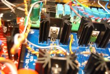
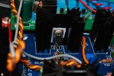
It's not a joke with thermal dissipation!! Two 2SK2013 just went to Valhalla after few days of continuous running. I had to reopen the case and drill some holes around the JC80 PCBs. i reduced also the Ids through the final MOSFETs to 80 mA (which is the lower limit regarding symmetrical voltages and also considering the sound). I measured the temperature after replacing the dead MOSFETS through the vents in the upper side of the case, just at the 2SK214 case, and after 2 hours, the temperature is 63 degrees Celsius, which I guess will be safe. Probably I can raise the Ids with few mA, but the sound is the same as with 100mA, and I would not take any chance to increase it further.
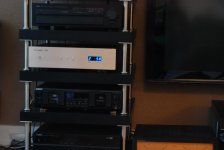
As some people asked me in PM's to take some pictures of my build, I did it now. Please check the attachments.
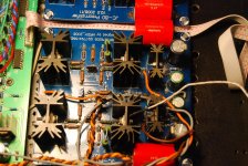
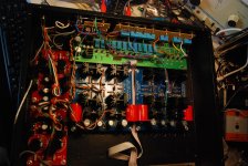
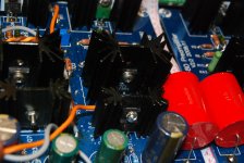
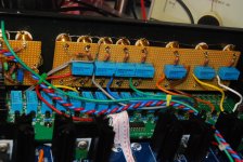
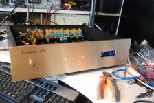
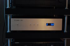
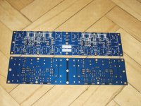
The blue pcbs are JC80 line amps, the red ones are Kubota regulators and the green one is the relay based atternuator. I moved the relays for source selection on a test board because the original has the unused inputs left open, while I wanted to have them connected to ground. Also, the power button of the case it's used now as a "Tape Monitor". You can also see the preamp integrated in my home-built audio furniture that's using cheap IKEA parts 🙂
Cheers!
It's not a joke with thermal dissipation!! Two 2SK2013 just went to Valhalla after few days of continuous running. I had to reopen the case and drill some holes around the JC80 PCBs. i reduced also the Ids through the final MOSFETs to 80 mA (which is the lower limit regarding symmetrical voltages and also considering the sound). I measured the temperature after replacing the dead MOSFETS through the vents in the upper side of the case, just at the 2SK214 case, and after 2 hours, the temperature is 63 degrees Celsius, which I guess will be safe. Probably I can raise the Ids with few mA, but the sound is the same as with 100mA, and I would not take any chance to increase it further.
As some people asked me in PM's to take some pictures of my build, I did it now. Please check the attachments.
The blue pcbs are JC80 line amps, the red ones are Kubota regulators and the green one is the relay based atternuator. I moved the relays for source selection on a test board because the original has the unused inputs left open, while I wanted to have them connected to ground. Also, the power button of the case it's used now as a "Tape Monitor". You can also see the preamp integrated in my home-built audio furniture that's using cheap IKEA parts 🙂
Cheers!
Attachments
-
 DSC_4362.jpg661.7 KB · Views: 685
 -
 DSC_4364.jpg572.8 KB · Views: 659
 -
 DSC_4366.jpg523.9 KB · Views: 633
 -
 DSC_4367.jpg403.9 KB · Views: 617
 -
 DSC_4368.jpg415.3 KB · Views: 606
 -
 DSC_4369.jpg558.5 KB · Views: 258
 -
 DSC_4373.jpg456.4 KB · Views: 256
 -
 DSC_4376.jpg283 KB · Views: 250
 -
 DSC_4375.jpg340 KB · Views: 253
Hi metallicus69,
Very nice work!
Very happy you like it. I am very satified of mine as well. I use the AMB Delta 1 and Delta 2 for source selector and volume control.
Hope more will join and try this build, it is really worth the efforts!
Ciao!
Do
Very nice work!
Very happy you like it. I am very satified of mine as well. I use the AMB Delta 1 and Delta 2 for source selector and volume control.
Hope more will join and try this build, it is really worth the efforts!
Ciao!
Do
Thanks Do!
I used the attenuator from diygene.com which matches the case from audiophonics. There is no way I can build such cases with my home equipment so I prefer ready-made solutions.
I also hope more will join, but that is why I posted details and my notes about thermal issues. This really should me regarded as a small power amp rather than a preamp when considering power dissipation of the devices.
Cheers!
Hi metallicus69
Great work. The simple preamplifier looks very complicated. You packaged many circuits in this case. It looks very nice. Congratulations!
Great work. The simple preamplifier looks very complicated. You packaged many circuits in this case. It looks very nice. Congratulations!
Thanks JKoch! There are not too many circuits;JC-80 (one for each channel) Kubota regulators (one for each channel) - these are the heat sources 😀 - one relay based attenuator (unfortunately not dual mono) with relay based source selection and the control module for this, mounted behind the front plate, that provides also the convenience of remote control.
What I also did was moving the selection of sources relays near the inputs and modifying the switching circuit to ground every unused input. Probably an overkill, but in my opinion this is the way input selection should be done.
All the primary sources (+/-40V for each Kubota and +15V for the atenuators) are located in a separate box to be able to cope with the space and electromagnetic field issues. It could not be any simpler considering my goals (remote control for example).
How is your design going? Did you confirm that your MOSFETS are genuine? Have you tried/will you try the cascoding of the outputs proposed by John? I am very interested in your results too 😉
Cheers!
metallicus69
In any way there are a lot of circuits. As I see you separated main PSU. This is a great idea. In my project all trafos and I stage of audio PSU will be in separate case (and PSU for control circuits too). It seems that main task of the JC-80 is heating the case. 🙂
I am still working on the JC-80 circuits. There will be both channels and output sockets (XLR, RCA and BNC) on one pcb. I will plan to use 2SK214/2SJ76 without cascoding. I am not an electronic so such circuits would be to difficult for me. The JC-80 pcb will take few days else. I will publish all schematics in this thread.
I am not experienced in such circuits like JC-80 and I do not know how to measure bias, in where point? Could you help me, please.
My MOSFETs: I checked them using diode tester only (see the web: Testing a MosFet). Maybe tomorrow or on Monday I will try to check them according to Nelson Pass (see attachment). The first simply test showed that they have proper pins like Hitachi (except one N-type MOSFET. It seems be damaged. If the will be genuine after the Nelson Pass test I will buy more them to chose best matched pairs.
Regards
Attachments
Hi JKoch,
On each MOSFET there is a source resistor, original 20Ohms, In my case still an acceptable 25 Ohm. You measure the voltage drop over it while adjusting the 200Ohms BIAS trimmer and apply the OHM's law. 2,5v/25Ohms = 100mA for example. If you correctly match the transistors and passive components, you will see very close values in all 4 source resistors. In my case I have 80mA and works like a charm. If you go higher it's better, as long as the heat has a way to run out 😀 😀. No need to go higher than 200mA I suppose. 70mA was too low in my circuit.
Good luck and keep us posted!
Nice work guys!
Keep up the good work!
I really want more people to try this build, it sounds really good.
Please also check this thread which we first started. I believe JC added some info in there as well.
http://www.diyaudio.com/forums/analog-line-level/200152-jc-80-ebay-pcbs.html
Ciao!
Do
Keep up the good work!
I really want more people to try this build, it sounds really good.
Please also check this thread which we first started. I believe JC added some info in there as well.
http://www.diyaudio.com/forums/analog-line-level/200152-jc-80-ebay-pcbs.html
Ciao!
Do
Last edited:
metallicus69
Thank you very much of the clean explanation. Here is schematic of left channel only. Second schematic will be include the right channel and third will be include L+R output sockets, power sockets, control sockets and trig pots. After I finish drawing I will post complete schematic. The name of the pcb is: Base Output Audio Board.
Next steps are: Input sockets + selector and attenuator - all dual mono. So finally my preamp will be totally dual mono from input to output and PSU. Apart of the preamp I am building Krell KSA-50Mk2 Clone (based on my pcb - copy of original one). The Mr. Krell will be dual mono from input to speaker and PSU too. I hope this dual mono configuration give my good spatial sound. In near future next project of DAC will be dual mono too.
Your opinion about sound giving by the JC-80 is very encouraging to further work.
Thank you again.
Attachments
Don't mention it! 😉
If something is not terribly wrong you should read same voltage values on N Bias and P Bias on the same branch. So voltage between NBias1L and V- should be equal to voltage between PBias1L and V+. Of course there are also the 10Ohm resistors between sides, (R6120 and P6101) but in case of good matching the currents flown through them are negligible compared to the main currents.
Yes, the sound is really fabulous after the first two hours, and improved day by day in extremely small steps. I believe in analog sound, mostly, so I never tried a digital source. I am interested as well to find a good DAC, as an important part of music I listen to stops in those silver 12cm CDs and does not get to black vinyl grooves...
A bit off topic:
I like good sounding music but unfortunately I listen CDs and DAT tapes only. Many years ago (20?!) I bought few black vinyls and rather not good turntable. But this "trip" was ended very short (caused by many out of music reasons):-(
Now I building with my friends music server including DAC. For the most important is DAC (I cannot imagine me to listen music tapping on keyboard or scrolling of mouse). So based on experiences get during building the music server I plan to build good sounding DAC for me. At this moment we have DAC sounds better than DAC assembled with Twisted Pair/Sabre kits (I assembled it device to get reference DAC to comparative tests). This is basic version. For me I plan build better DAC, on similar circuits, but using high quality components. We compared our DAC with few others and CD players and e.g. our DAC sounds far better than top belt-drive CD player of C.E.C. and a bit better than Musiland.
Sorry for too long off topic. If you interested to discuss about it, send me PM please.
Off topic: Sure, I am interested, but for the moment I am focused on my next projects, VSSA and next the balanced one or XVSSA (I had an idea on how to make that one balanced to match the full capabilities of this great preamp). The soldering iron cannot stay cold too long, have no idea why 😀
Your Krell is balanced? (sorry for my ignorance, but I haven't studied the schematics of Krell's)
A nice DAC of course can be a great future project... but at the right time. With close to one thousand of vinyls around me it's hardly a top priority now 😀
Your Krell is balanced? (sorry for my ignorance, but I haven't studied the schematics of Krell's)
A nice DAC of course can be a great future project... but at the right time. With close to one thousand of vinyls around me it's hardly a top priority now 😀
Hi metallicus69
Krell KSA-50Mk2 is not balanced but sounding great. BTW DAC: the project will be realized in future too. Now I have too much opened projects like you.
It is time to back JC-80. I hope finish pcb in 1-2 weeks.
Regards
Krell KSA-50Mk2 is not balanced but sounding great. BTW DAC: the project will be realized in future too. Now I have too much opened projects like you.
It is time to back JC-80. I hope finish pcb in 1-2 weeks.
Regards
Hi Dominic
I have a question for about the "JC-80 eBay PCBs & Power Train" thread: I cannot open any other pages except first. After attempt to open any other page I get answer "Page not found". Could you try to open any page of the thread? Send me any answer in last post and to PM. Thank you.
I have a question for about the "JC-80 eBay PCBs & Power Train" thread: I cannot open any other pages except first. After attempt to open any other page I get answer "Page not found". Could you try to open any page of the thread? Send me any answer in last post and to PM. Thank you.
I have finished the JC-80 preamplifier schematic. In my preamplifier it will be output module including JC-80 left+right channels and output sockets. There will be placed three sockets to connect it to separated power supply unit. The board include three types of sockets: XLR, BNC50 Ohm and RCA. They are grouped in three types: variable outputs (regulated by attenuator module), fixed outputs (directly connected to input selector module) and record outputs (fixed outputs switched on/off to connect my DAT Tape Deck). Here is a set of schematics. I just started to design of the pcb. Dimensions of the board will be:long 370mm and width max 130mm (maybe less).
Attachments
I have finished the JC-80 preamplifier schematic. In my preamplifier it will be output module including JC-80 left+right channels and output sockets. There will be placed three sockets to connect it to separated power supply unit. The board include three types of sockets: XLR, BNC50 Ohm and RCA. They are grouped in three types: variable outputs (regulated by attenuator module), fixed outputs (directly connected to input selector module) and record outputs (fixed outputs switched on/off to connect my DAT Tape Deck). Here is a set of schematics. I just started to design of the pcb. Dimensions of the board will be:long 370mm and width max 130mm (maybe less).
Nice work!
What are your plans as far as volume attenuation?
Ciao!
Do
- Home
- Source & Line
- Analog Line Level
- JC-80 eBay PCBs & Power Train