One point about its design itslef. the output of the op amp dont have any level shift, it is done with caps. It is done thru C2 and R3/C9. I have figured on my bread board that the swing of the op amp was not low enough so the gate driver was seign always a logic "1" at its input. Maybe something is needed there. I managed to make it work with some pull down resistor at the input of the gate. 100k was good enough. If not present, it was making the output stuck to -vcc, almost like when it was new 😀
It worked on my bread board, do you remember ?
hahahahaha !!!!
It worked on my bread board, do you remember ?
hahahahaha !!!!
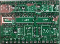
Yes, that is correct for the layout Pat, except for one mistake, on my part....
 D8 and D9 are 1n4150
I have it down on my paper right, but when I typed it into the graphic, my dyslexia kicked in. I have them down on the schematic as 1n5140. Please accept my apology for the mistake!
BUT here is the good news:
the cap C3 that is marked with just a 47 is indeed 47 pico!
And I tested the ICs and both schmitt inverters are perfectly ok, so there goes the theory on the 6V being too stressful on them.
The ONLY 2 bad components were of course the IRL640's...those are direct shorted between Drain and Source. I already had that figured just for the fact that the 2A fuse on the main board was blowing immediately!
Hope this helps ya'll...
I ordered up the parts today, so they should be here by week's end hopfully. For the start I am just going to rebuild the circuit as it was, no potting, much better heatsink and see how it goes.
Jer
D8 and D9 are 1n4150 I have it down on my paper right, but when I typed it into the graphic, my dyslexia kicked in. I have them down on the schematic as 1n5140. Please accept my apology for the mistake!
BUT here is the good news:
the cap C3 that is marked with just a 47 is indeed 47 pico!
And I tested the ICs and both schmitt inverters are perfectly ok, so there goes the theory on the 6V being too stressful on them.
The ONLY 2 bad components were of course the IRL640's...those are direct shorted between Drain and Source. I already had that figured just for the fact that the 2A fuse on the main board was blowing immediately!
Hope this helps ya'll...
I ordered up the parts today, so they should be here by week's end hopfully. For the start I am just going to rebuild the circuit as it was, no potting, much better heatsink and see how it goes.
Jer
yeah, i found out that 5140 dont exist in my data book...i have stuffed my board just right now, i will fire it up tomorrow...
thanks.
thanks.
Something new caught my eye, I'll get to it later.
First to comment on the the use of an op amp as a comparator.... blech.
Second to comment on the pull down thing. This is interesting. I have to point out that while on the breadboard, you weren't sure of all the values to use, so that will change things significantly, as will the use of a breadboard to begin with, but, I still think it is an excellent point. It would seem that whole section is floatingm, not too smart. Perhaps a 10K pull down would be best placed between C2 and R3. If that's left to float a really ugly condition can occure where it sits near it's threshold and bias both it's output devices into Class A, .... meltdown. Being a schmitt trigger though, it would like switch spurriously, I'm not sure how fatale this would be while the amp is turned off, probably not very. Whatever, a 10K is cheap insurance.
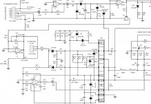
D6 and D7 ..... rectifiers? Disgusting. They should have a low voltage drop, either small signal or the more expensive shottky's, more importantly, they need to be fast recovery, which these are claimed to be, for a rectifier. But, a fast recovery "rectifier" with a ~200ns reverse recovery time just isn't fast recovery for this job. No rectifiers allowed. 2ns to 4ns is alot more like it! I would be changing those to something more suitable for the application. It isn't a big deal for D7 at all, but they should be the same, the only purpose of D7 is to provide the same voltage drop as D6 produces, helps keep things in equilibrium.
Here's the other part that caught my eye that I'm getting to now.
The inverters are different.
Pat's used MC74ACT14AN, part of the ACT family, so what's the difference? VCC _recommended_ max for the ACT family is 5.5V. While for the AC family it is 6V. They're both spec'd to flat line at 7V VCC... or VDD rather.
Not a huge difference. It seems they went with logic level mosfets and gave themselves a bit more headroom on the driver supply by going to the AC family, it won't save them if they aren't bypassed.
The other difference, is their input thresholds. ACT is a TTL compatible family, which means it has a Vth of 1.5 or1.2 volts, the data sheet shows different values because it is a device with hysteresis, therefore showing thresholds of .8 and 2volts.
While for the AC, Vth is supposed to be VDD/2. The data sheet specs it at a min of 1.1 and 3.9V.
These are all given at a VDD of 5.5V. So basically the AC family, is a little more at home operating at 6V VDD, and has better noise immunity at the input.
Either way, proper bypassing of them is critical. Did I say they should be well bypassed? I think they should be well by passed.
Regards
PS:
Don't forget to bypass them.
First to comment on the the use of an op amp as a comparator.... blech.
Second to comment on the pull down thing. This is interesting. I have to point out that while on the breadboard, you weren't sure of all the values to use, so that will change things significantly, as will the use of a breadboard to begin with, but, I still think it is an excellent point. It would seem that whole section is floatingm, not too smart. Perhaps a 10K pull down would be best placed between C2 and R3. If that's left to float a really ugly condition can occure where it sits near it's threshold and bias both it's output devices into Class A, .... meltdown. Being a schmitt trigger though, it would like switch spurriously, I'm not sure how fatale this would be while the amp is turned off, probably not very. Whatever, a 10K is cheap insurance.
D6 and D7 ..... rectifiers? Disgusting. They should have a low voltage drop, either small signal or the more expensive shottky's, more importantly, they need to be fast recovery, which these are claimed to be, for a rectifier. But, a fast recovery "rectifier" with a ~200ns reverse recovery time just isn't fast recovery for this job. No rectifiers allowed. 2ns to 4ns is alot more like it! I would be changing those to something more suitable for the application. It isn't a big deal for D7 at all, but they should be the same, the only purpose of D7 is to provide the same voltage drop as D6 produces, helps keep things in equilibrium.
Here's the other part that caught my eye that I'm getting to now.
The inverters are different.
Pat's used MC74ACT14AN, part of the ACT family, so what's the difference? VCC _recommended_ max for the ACT family is 5.5V. While for the AC family it is 6V. They're both spec'd to flat line at 7V VCC... or VDD rather.
Not a huge difference. It seems they went with logic level mosfets and gave themselves a bit more headroom on the driver supply by going to the AC family, it won't save them if they aren't bypassed.
The other difference, is their input thresholds. ACT is a TTL compatible family, which means it has a Vth of 1.5 or1.2 volts, the data sheet shows different values because it is a device with hysteresis, therefore showing thresholds of .8 and 2volts.
While for the AC, Vth is supposed to be VDD/2. The data sheet specs it at a min of 1.1 and 3.9V.
These are all given at a VDD of 5.5V. So basically the AC family, is a little more at home operating at 6V VDD, and has better noise immunity at the input.
Either way, proper bypassing of them is critical. Did I say they should be well bypassed? I think they should be well by passed.
Regards
PS:
Don't forget to bypass them.
charger_1 said:Yes, that is correct for the layout Pat, except for one mistake, on my part....
I have it down on my paper right, but when I typed it into the graphic, my dyslexia kicked in. I have them down on the schematic as 1n5140. Please accept my apology for the mistake!
BUT here is the good news:
the cap C3 that is marked with just a 47 is indeed 47 pico!
And I tested the ICs and both schmitt inverters are perfectly ok, so there goes the theory on the 6V being too stressful on them.
The ONLY 2 bad components were of course the IRL640's...those are direct shorted between Drain and Source. I already had that figured just for the fact that the 2A fuse on the main board was blowing immediately!
Hope this helps ya'll...
I ordered up the parts today, so they should be here by week's end hopfully. For the start I am just going to rebuild the circuit as it was, no potting, much better heatsink and see how it goes.
Jer
Well I just explained the difference of the inverters so I'm stickn to my guns 🙂
Maybe some added snubbing across the mosfets will be enough to save them.. I hope you have a scope and check out how clean they switch an the like.
Good luck with it all.
So id better find AC chips and IRL mosfets...sounds like my module were having the worst of it all 
Say I was going to ask, what were you suggestiong for snubbing the mosfets? They already have an internal diode for snubbing....were you suggesting adding a second diode? An RC network? I was just curious!
Jer
Jer
Hi, i did work on the preamp part of this stupid sub today. Many parts are toasted, almost all the diodes into the muting circuit were short.
D10,11,12,14
C42 was short as well.
It work ok now (just the preamp section), but i am wondering about something: the op amp just before the module (pins #8-9-10). If i inject a simple 100hz sine wave, it goes thru ok until it goes thru that op amp, then the output signal appears flattened, but still something sine wave. Duno the purpose of this.
also, the vcc rails for the op amp, as well as the rails for the module, are very badly filtered. So i did add some caps. It looks like it will work far better with this addition.
also, i did all the required reworks as per the lates service manual.
I may make it work on its own tonight...
Attachments
Yeah, so much for waiting for all the parts to get here... I have most of them so I've started stuffing my board. Since I have a few days, I might just as well take a peek at the mainboard, and see if my rem turn on is cooked as well.
Here's a thought, relating somewhat to my previous thought on the amp module frying due to being turned on even with no signal input... if i'm not mistaken it's a fact that these mosfets will fry if they are on, but not modulating... if the remote turn on goes out, and tells them to stay on all the time.... get what i'm getting at? If my remote on is bad as well, i'm really going to start thinking that way again.
Did you ever run the speaker off a separate amp to make sure you didn't take that out? I figured before I put a penny into mine, I should check to see if it's even worth it... and good news!
I think I'm going to take and piggyback a .1uF across the IC's power rails... it's not going to hurt anything one bit, and might help things out in the long run.
Tomorrow I am going to see if I can start machining my new heatsink. I didn't have much time today at work... hate busy days, can't get my home projects done!
I'll keep ya'll posted as things develop
-Jer
I may be mistaken, but that darn thing is always "on", so even if the mute circuit is dead, the amp module always runs 100khz (if it is not burned 😀 ). As soon as it is powered, it start 100khz 'ing, audio or not, mute ok or not. The only way it goes off is when the power switch is off (stop oscillating) , or when the short circuit is activated.
Mine blew while it was under mute (red leds on the faceplate), so the muting circuit was activated. There is nothing that realy goes off when it is muted other than a fet that short the audio path and a bank of leds that change color. Talk about something bad. They could have at least put a relay or something....
Mine blew while it was under mute (red leds on the faceplate), so the muting circuit was activated. There is nothing that realy goes off when it is muted other than a fet that short the audio path and a bank of leds that change color. Talk about something bad. They could have at least put a relay or something....
Yup, that sounds exactly like what most people have complained about...it was muted when it failed.
Here is the good news, After seeing and hearing how these things fail when in mute mode, I am going to build a simple 20A relay box in a standard j-box, and hook one plug into the wall, one plug to the back of my stereo switched output, and the socket to the sub.... no more guessing here! Aw I'll also add a nice little neon light so I know when it's on 🙂
Jer
Ok, here is an update... my board is assembled and installed, kept it all stock for now. What I did differently tho is I added a nice little mod to the cooling capabilities!
Yesterday while messing with an OLD laptop, I ended up cooking the CPU, so low and behold, I had this really nice low profile, light weight, excellent thermo-conductive piece of aluminum, and it came with a really cool little 5V fan!
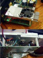
So, here is my MOD for the cooling, I put both hexfets under the heatsink, used isolation pads and thermo grease, then I also added a +5V regulator (on the left side of the image) so my fan can tap the +15 from the op amp and step it down to something the fan can handle. I used 2" lengths of 18ga wire to jumper to the mosfets and used heat shrink over the connections so hopfully it won't arc.
My bench test outside of the speaker cabinet was a success! At that point I took the pics, and sent them to you guys! Now, for the big test...it's going in and getting thumped! (hopfully). I will let ya know how it turns out
Enjoy the mod pics!
Jer
Yesterday while messing with an OLD laptop, I ended up cooking the CPU, so low and behold, I had this really nice low profile, light weight, excellent thermo-conductive piece of aluminum, and it came with a really cool little 5V fan!
So, here is my MOD for the cooling, I put both hexfets under the heatsink, used isolation pads and thermo grease, then I also added a +5V regulator (on the left side of the image) so my fan can tap the +15 from the op amp and step it down to something the fan can handle. I used 2" lengths of 18ga wire to jumper to the mosfets and used heat shrink over the connections so hopfully it won't arc.
My bench test outside of the speaker cabinet was a success! At that point I took the pics, and sent them to you guys! Now, for the big test...it's going in and getting thumped! (hopfully). I will let ya know how it turns out
Enjoy the mod pics!
Jer
Attachments
Nice...
You might wana check if the +15vcc will not drop, it is very poorly regulated, there is no electrolityc cap or so, only very few 100nf caps, loaded with 3x 10k parralel and a 15v zener...
By only making it play with the crossover (no power module), a lot of variations was visible on the op amp rails. I cant imagine what it could be with the power module and full power. perfect recipe for toasting. adding another load on this (fan) might affect it too much.
As an initial test, i added a 470uf cap on both op amp rails...already far better..."real" regulators are on call in mine.
HOL* "/%
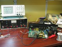
This stupid thing works...I made a caption of the set-up, and a snap shoot on the scope. It oscillates at 75khz, wich is lower than it is suposed too, 100khz.
One thing remains obscure: Once it is turned off, you have to wait very long before it will restart ok.
If you turn it off, and on before the caps are fully discharged, it wont turn on, and stuck to -vcc  😡
😡
There is something bad with the start-up and the bootstrap chargeup, wich is controled with the SD signal, i will work on that...
Now, let make it play (and install the heat sink)
This stupid thing works...I made a caption of the set-up, and a snap shoot on the scope. It oscillates at 75khz, wich is lower than it is suposed too, 100khz.
One thing remains obscure: Once it is turned off, you have to wait very long before it will restart ok.
If you turn it off, and on before the caps are fully discharged, it wont turn on, and stuck to -vcc
😡 There is something bad with the start-up and the bootstrap chargeup, wich is controled with the SD signal, i will work on that...
Now, let make it play (and install the heat sink)
Attachments
Well, maybe i'm not supposed to have this amp working after all!
Had several "issues" with assembly....
First, I put both mosfets in backwards... (don't ask)....
Then once i got that corrected, still no sound so I was probing for voltages and in the process lost control of the meter leads.... there goes a nice little spark!....
Replaced the op amp and noticed a solder bridge from one of the schmitt inverters to ground... hmm... fixed that pluged it in and there went the fuse!
Ok, sniff out the bad mosfet, replace it... (only had one left or they would both have been replaced)... plugged it in and.... SOUND!!!! but you know what? no music! It doesn't matter what I feed it...all it does is HUMMMMMMMMMMMMM.....................
So, I think it's time to take a break from it for a few days. I've only had time to work on it between calls at work, and believe me, time is limited there... so that is where the mistakes came from...
Here is the strangest part... even with the mosfets backwards, nothing got hot or blew, and the lights on the front of the unit worked properly.... now that everything is "right", it never goes into standby....go figure.
Here's one that if someone could check theirs for me, I would appreciate it....
Checking DC on the + and - I get somewhere along the lines of 198V... but if I switch to the AC scale.... 409V!!!! Yet both c1 and c2 check ok...Does this seem normal???
Pulling 10 hour shifts for the past 23 days straight has me about frazzled, and I have another 12 days to go, so I'm sure I'm missing something simple and stupid... input would be appreciated.
(oh and just in case you were wondering... I disconnected my cooling fan for the purpose of getting this running FIRST then cooling it LATER)
Jer
Hi,
Been there! Good tip, which I never do but reaaally should, tape off the meter leads and just leave the very tip exposed, reduces chances of shorting something out if you slip.
If at all possible I avoid that totally by using clips, then turning the power on, then measuring.
It's a good idea to take a break from it, and in the meantime you can order more mosfets, it gets to a point where it doesn't matter what you do it's wrong or backwards or.. ya know, just gets silly after awhile, especially when very tired.
I think Pat's amp had 90 volt rails, ~180 total=what each mosfet has to block. You have 198, add some ripple.... hmmm scary, doesn't seem like much of a margin in either case, those are only 200 volt mosfets.. is that with no load? Try measuring them again, on DC scale, but no modulator or anything, just see what the rails on their own are.
The rail to rail ripple is probably messing with your meter on AC range, it's not like setting a scope to AC where you can read the ripple that's riding on the DC.
Is your hex inverter that had a solder bridge still good?
At this point, you need to take your time and go over every component again, triple check every component for a tenth time.
If you had a another supply to test with or something, take all the other junk (supplies, mute junk, shut down junk, etc) out of the equation, just work out the problems with the modulator itself to start with, that'd be a big help for you.
I'm still not certain of what you had done with those two wires to the mosfets you mentioned, had you relocated them to get them to the heatsink ? Bad move, would add extra inductance by increasing the current loops from driver-mosfet-ground-supply..
Try and fix it up so it's exactly as it was and working, then concentrate on making one improvement at a time.
If you're hearing hum like that though, I think the mosfets are finished, check them again. It's rare that only one of the pair goes, haven't seen it happen yet.
Regards,
Chris
EDIT:
When mosfets go they usually take the driver out with it, all three pins of the mosfet short out, put an ohmeter across any given pin and it'll read 0, connects the rails to the drivers, smokes em most of the time.
I'll try to answer your questions as best i can:
My DC readings were with no load, no input. That was straight off the rails, after the caps. Likewise with the AC.
I haven't checked the hex inverter...yet. I suspect that the one that had the bridge may have suffered damage. I haven't taken the module out of the board since it happened... decided it was time for some brew and a relaxing evening LOL
I am taking a chance at adding what is now about 1.5" worth of lead to each leg of the mosfet to the pcb where it originally attached. At this point in time I have little choice, it's more to get the item operational, and then I will work on the fine tuning. I am considering building a small daughter board to attach to the amp module board, and having a heavy ground plane and attaching the mosfets to that instead. That would cut interferance greatly, but I just need to get this item working first.
I suspect the mosfets are gone (at least the one I didn't replace) even though it tested with no shorts what so ever. Of course, then again, the mosfet tha blew the fuse had no detectable shorts either 😉
I did notice that when the hum starts, the cone pulles inward, so that would signify that the mosfet tied to the negative rail is what is doing the dirty deed
Jer
Hi.
About the stand-by... you may read the entire document i sent you.
It takes 15 minutes at least to go into standby mode, after power-up.
For troubleshooting, connect an oscilloscope on the output of the amp, without the speaker. Look what the output does at power up. Mine is making 2 big shouts +vcc -vcc, clearly audible into the output inductor (tic tic), and then starts to oscillates.
As mentioned, if i turn it on too fast after beign turned off, it wont turn on, making -vcc to the speaker, and yes then hummmmmmmmmm.
As initial test, i did connect the complete board on a external power supply, with only 35 volts rails, limited at 1amp. Also, i have instaled temporarily sockets for all the chips. If you want to by-pass the stand by mode, remove c42, but it wont affect the turn on at all, wich is your problem i guess.
i measured that when it doesn want to turn on properly (hummmmmmm), the bootstrap is not charged at all.
I my case, i think i have put too big caps onthe opamp rails, wich are common to the opwer module opamp rail too, so they remains charged while the main caps are not, it may not help at all for the fuzzy turn-on procedure... 😕
hth
- Home
- Amplifiers
- Class D
- JBL PB12 subwoofer, Class D amp, dead.