That is not "horizontal DI". It is directivity index which is calculated in both planes, and the wiggle is coming from vertical plane - as already told.
OK, but the headline of the graphics I quoted is "Directivity (hor)" Misleading!
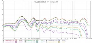
Xrk, my guess too is that not-so-perfect time alignment and not-so-perfect slopes are causing most of the response wiggles around xo. LR4 makes narrow transition zone, perhaps softer LR2 might give smoother responses.
I still want to copy the waveguide shape, it works well despite the dip in on-axis above 10kHz. Plastic wrap folio as protection, alginate impression, then gypsum cast to make a mold... I am familiar to this by my profession! Patrick Bateman is making 3D models, but I don't have a printer...
but the headline of the graphics I quoted is "Directivity (hor)" Misleading!
Yo Mama is misleading!!! 😀 Chart title is located just above the graph on white background. You snapped also title of surface chart below gray border area, and that graph is horizontal directivity - as title tells.
OK, but the headline of the graphics I quoted is "Directivity (hor)" Misleading!
Xrk, my guess too is that not-so-perfect time alignment and not-so-perfect slopes are causing most of the response wiggles around xo. LR4 makes narrow transition zone, perhaps softer LR2 might give smoother responses.
I still want to copy the waveguide shape, it works well despite the dip in on-axis above 10kHz. Plastic wrap folio as protection, alginate impression, then gypsum cast to make a mold... I am familiar to this by my profession! Patrick Bateman is making 3D models, but I don't have a printer...
I like casting too. I made a copy of an RC fiberglass tunnel hull race boat once as a kid. Used concrete for the mold. 🙂
Just for information, wave guide of LSR308 is a bit better with dome than 305, but both not worth to clone imo.
Yo Mama is misleading!!! 😀 Chart title is located just above the graph on white background. You snapped also title of surface chart below gray border area, and that graph is horizontal directivity - as title tells.
Sorry, it was my mistake really! Sometimes we get blind to what we see.
I am planning to use a 4" mid with this waveguide and cross it around 3,5-4kHz. I have a pair of Peerless neo/aluminium domes. Well, now I have these 305s to be used as models. If or when I make a mold/cast, tweaking of it's shape begins! Children's plastic clay or plumber's putty can be used for testing different shapes. Suitable recession is also important, to get timing to match as well as possible
Did anybody any amp modernization? Electrolytic capacitor upgrade or etc.?
I would check all 4? regulators and how they are used here.
Also speakerinput only takes xlr and jacks, funny thing is the AD converter used only takes single ended signal, so why don't they offer cinch input ?
Amp used with 19V (one of the regulators) here that makes 15w 8ohm 1% THD for tweeter and around 20W for woofer. What is raw voltage from SMPS ?
They tried to make it as cheap as possible, the goal being even spreadig-prossession of sound. To my ears it's very good for money, but i'll do some improving.
My finnish friends, did you read the test of active monitors in Hifimaailma 2/2012? Subjective responses vs measurements?
My finnish friends, did you read the test of active monitors in Hifimaailma 2/2012? Subjective responses vs measurements?
At least I did. It was blind test which was something new and funny for a long time. Speakers with the worst measurements did not win.
Last edited:
I read it too, but can't remember results. I mostly skip listening impressions in magazines. They are unreliable and often just boring, decorated and prolonged stories of the author's favourite artists and recordings.
One member of the group had been sound pro for 20 years and now was a mastering specialist. His responses vs measuremets were rearkable.

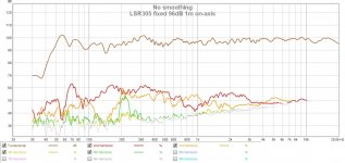
My guess for that midrange distortion is mechanical resonances from circuit board that IS connected to The metallic Back wall.
One member of the group had been sound pro for 20 years and now was a mastering specialist. His responses vs measuremets were rearkable.
If I remember correctly people on our local forum were quite pleased that these "mastering specialists" don't design and ruin speakers or other audio equipment. They can ruin only records we listen 😀
Electronic modifications
Hello together
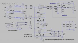
For those who want to look a little deeper into Electronics I have extracted Schematic from Analog section.
- Coupling Capacitors to Opamp are Electrolytic Type 100uf. I do not believe
that Film Caps sound better. Nevertheless I changed them because of
reliability. I had already several Electrolythical caps in the past which get
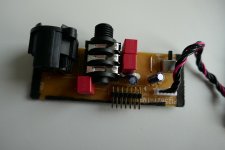
"dry" with the time. Attached Picture shows Wima Foil caps with 6,8uF.
Space is very limited, bending of Lead wires is necessary.
- OPamp Mod. Used OPamp is NJM2115. I did not change because I do not
believe in Sound difference of OPamps.
Mods that have effect on Sound:
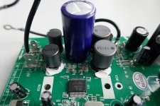
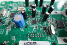
- Buffer capacitor change of STA350BW changed form 1000uF/35V to
4700uf/35V (Dark Blue Capacitor, please refer to attached picture)
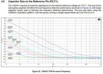
- Capacitor on Filt+ Pin of CS5341 AD Converter:
According to latest Datasheet of CS5341 100uF decreases Distortion Level
at low Frequencies dramatical compared to used 1uf in current PCBA
(Light blue capacitor, please refer to attached picture)
How does it sound compared to unmodified Electronic:
More Punch and cleaner sound. Test it
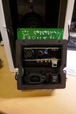
Some hints for assembly:
- It is not easy to assemble "Analog section back to mainboard. Therefore
suggestion is to assemble first black cover of Analog section and then slot
in Analog electronic with visual inspection if all Pins are in right connector
inserted. It is possible to shift to left and right by one.
Have fun
Eljo
Hello together
For those who want to look a little deeper into Electronics I have extracted Schematic from Analog section.
- Coupling Capacitors to Opamp are Electrolytic Type 100uf. I do not believe
that Film Caps sound better. Nevertheless I changed them because of
reliability. I had already several Electrolythical caps in the past which get
"dry" with the time. Attached Picture shows Wima Foil caps with 6,8uF.
Space is very limited, bending of Lead wires is necessary.
- OPamp Mod. Used OPamp is NJM2115. I did not change because I do not
believe in Sound difference of OPamps.
Mods that have effect on Sound:
- Buffer capacitor change of STA350BW changed form 1000uF/35V to
4700uf/35V (Dark Blue Capacitor, please refer to attached picture)
- Capacitor on Filt+ Pin of CS5341 AD Converter:
According to latest Datasheet of CS5341 100uF decreases Distortion Level
at low Frequencies dramatical compared to used 1uf in current PCBA
(Light blue capacitor, please refer to attached picture)
How does it sound compared to unmodified Electronic:
More Punch and cleaner sound. Test it
Some hints for assembly:
- It is not easy to assemble "Analog section back to mainboard. Therefore
suggestion is to assemble first black cover of Analog section and then slot
in Analog electronic with visual inspection if all Pins are in right connector
inserted. It is possible to shift to left and right by one.
Have fun
Eljo
Attachments
Is it possible to mod the speakers to take a digital input? I guess that it would be an improvement.
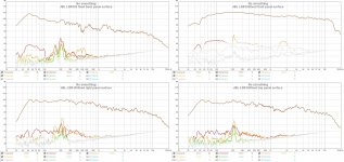
I made some better quality measurements. This is a really nice active speaker for the price! Well worth opening and adding a cross-brace!
Do you have any ideas why bracing smoothed frequency response, but increased distortion?
Yes I do. Because those two measurements are not directly comparable at all! They were taken in different environment, different distance, different signal level. First one was just a quickie because cabinet resonance was so annoying that I had to do something any way. Posting those findings occurred to my mind later on. The "better" measurement was done by my own stardard procedure and environment.
Last edited:
Found this interesting blog post that you guys might appreciate. JBL LSR305 Teardown and Analysis
One particular bit I'm interested in is a possible fix for the tweeter hiss. The guy notes that ;
"Unfortunately the tweeters produce audible hiss in a quiet room. Looking at the back side of the board reveals at least one problem - there is a large ground plane that transfers the 400 kHz parasitics from the power amp to the analog input, including the ADC. JBL should have used the standard in audio star topology to isolate the power section from the analog section. The electric noise fed into the tweeter is a lot stronger than appears to the ear - I measured 1 VPP on the speaker terminal in respect to ground with an oscilloscope. The majority of the noise power is in the inaudible range."
I'm curious if anyone has an idea on how to remedy this. Perhaps additional grounding or filter caps?
I have tried adding copper EMI shielding tape around the analog input board, total waste of time...
Last edited:
I listen to my 305's near field, and they are really quiet, I don't hear any hiss or noise like he describes.
I have heard other reports of hiss though.
Do you guys have that problem?
I have heard other reports of hiss though.
Do you guys have that problem?
- Home
- Loudspeakers
- Multi-Way
- JBL LSR305 tweaking