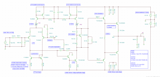
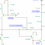
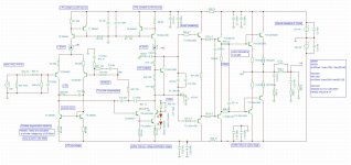
Removing paralleled output transistors actually makes it JAT501 with added one extra transistor (not counting ccs) and two pole compensation parts.
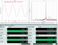
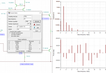
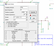
thd improved to 0.0014%
thd improved to 0.0014%
Attachments
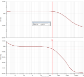
Not sure how to do bode plot to see the phase margin

There is this crazy amp by Topping that is able to do 0.0001Problem is the parts count for this topology is rather high to get the usual
.001 % distortion. And With compensation to keep it stable at high Frequency.
Dont expect more than usual .01% to .05% or lower at 20 kHz
Is error correction has something to do with that?
https://www.audiosciencereview.com/...topping-la90-discrete-amplifier-review.43756/
Attachments
Might be, there is few tricks
Keep the amplifier gain low.
Composite amplifier. Dual Diff , Complementary Cascode Vas
Or yes Power section is basically a follower. So if you can add feedback
/error correction around the output section.
even just Direct coupled or no capacitors in feedback.
Lots of ways to do it.
I can direct couple the simple amp I posted earlier
and set the gain very low. Which does it at 1 kHz
Distortion is -86 dB at that point
at high frequency, probably not, closer to .003%
which puts highest harmonic about -70 dB
Additional feedback / error comp would likely do it.
With preamp and tone filters and highpass for sub.
its rather pointless to care. distortion is meaningless
at that point. with CD playback or bluetooth stream.
blah.. distortion way above even a simple amp.
With preamp and tone filters and highpass for sub.
its rather pointless to care. distortion is meaningless
at that point. with CD playback or bluetooth stream.
blah.. distortion way above even a simple amp.
bunch of DACs are 0.0001
but other than fun yeah, no point...
like having a 600hp car that sits most of the time in the garage, just fun lol ...
probably will not be able to hear the difference, but who knows...
Last edited:
By the way, most of those DACs are balanced.
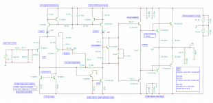
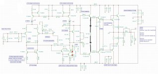
I wonder if using power amplifier as differential amp is a good idea?
CMRR should be good for input LTP with CM and CCS?
Probably will need DC couple Va and Vb (pic below)

I wonder if using power amplifier as differential amp is a good idea?
CMRR should be good for input LTP with CM and CCS?
Probably will need DC couple Va and Vb (pic below)
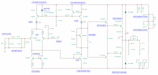
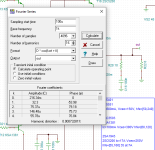
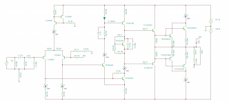
And here is the version that accomplishes lowest THD
0.00073 into 8 ohm
0.00099 into 4 ohm
technically this is 801, with over 200W of power into 4 ohm
0.00073 into 8 ohm
0.00099 into 4 ohm
technically this is 801, with over 200W of power into 4 ohm
Attachments
But how to determine resistance of the next stage?ability to drive the next stage.
I know that BJTs in OPS are harder to drive vs MOSFETs
So my assumption I need to look at the data sheet?
Do you mind posting schematics?I can direct couple the simple amp I posted earlier
and set the gain very low. Which does it at 1 kHz
Distortion is -86 dB at that point
at high frequency, probably not, closer to .003%
which puts highest harmonic about -70 dB
Additional feedback / error comp would likely do it.
Look up the Hfe and compute the base current.So my assumption I need to look at the data sheet?
Ed
Hi. How to add models 2SC4793A, 2SA1837A or 2SD669A, 2SB649A, instead of KSC3503, KSA1318 (BD139, BD140) to this amplifier?
In the pre-output stage, it is necessary to put more powerful transistors so that there is no quasi-saturation.
In the pre-output stage, it is necessary to put more powerful transistors so that there is no quasi-saturation.
Attachments
Hi. How to add models 2SC4793A, 2SA1837A or 2SD669A, 2SB649A, instead of KSC3503, KSA1318 (BD139, BD140) to this amplifier?
.MODEL 2SD669A NPN (BR=0.0116 CJE=1.5E-10 CJS=0 EG=1.11 FC=0.5 IKF=0.403 IKR=1 IRB=1E-06 IS=6.73F ISC=1E-13 ISE=1.14E-14 ITF=9.99 MJC=0.407 MJE=0.33 NC=2 NE=1.04 NF=0.8 NR=1.03 RB=4 RBM=0.761 RE=0.00255 TR=0 VAF=25.1 VAR=50 VJC=0.3 VJE=0.75 VTF=1E+06 XTB=3.82 XTI=2.5 BF=3.350000E+02 CJC=6.110000E-11 RC=5.550000E-01 TF=9.010000E-10 XTF=4.450000E+01)
.MODEL 2SB649A PNP (IS=293.5F BF=216 NF=1.0 VAF=40 IKF=1.5 ISE=101.1P NE=2.6797 BR=7 NR=1.0 VAR=20 IKR=0.05 ISC=1.345P NC=1.5558 RB=0.46 RBM=0.46 RE=5M RC=1.07 CJE=295.4P VJE=0.6977 MJE=0.5197 TF=0.8569N XTF=53.4 VTF=2.83 ITF=1.22 CJC=113.1P VJC=0.5466 MJC=0.5742 XCJC=0.5 TR=14.65N XTB=1.87 EG=1.11 XTI=3.0 FC=0.5)
.MODEL 2SC4793_E NPN IS=1.8E-09 NF=1.43 BF=146.38 VAF=273 IKF=2.6 NK=0.95 ISE=6.286997E-10 NE=2.223629 BR=4 NR=1 VAR=20 IKR=1.05 RE=0 RB=1.7 RC=1.25 CJE=5.96964E-10 VJE=1.1 MJE=0.5 CJC=5.78E-11 VJC=0.3 MJC=0.3 TF=1.22678E-09 FC=0.5 ITF=10 XTF=99.52253015 TR=983N
.MODEL 2SA1837_E PNP IS=2.39372559E-10 NF=1.304015937 BF=300 VAF=273 IKF=2.087725944 NK=0.94719458 ISE=1.46829699E-11 NE=1.526663542 BR=4 NR=1 VAR=20 IKR=1.05 RE=0 RB=1.8 RC=1.65 CJE=4.7407E-10 VJE=1.1 MJE=0.5 CJC=8.6700E-11 VJC=0.3 MJC=0.3 TF=1.642191E-09 FC=0.5 ITF=1.076260106 XTF=5.868994022 TR=1.38U
Just make a text file for each, then, tools create macro from a file, follow the prompt
If you have macros files already you can add them at edit or insert - macro
If you have macros files already you can add them at edit or insert - macro
How did you get such low distortion?Doing a very simple model , and comically tossing in a diode
bias string LOL. This classic topology below will perform same results
or better, with tremendous reduction in parts count.
I have put it together, but I can only manage 0.04
Attachments
- Home
- Amplifiers
- Solid State
- JAT501 simulated using TINA TI and possible improvements