so i have 4 open issues/questions:
1. CCS with LED can i use a smal cap to stabilize
2. for R6 (LTP) can i use 2 parallel resistors with about 1k5 to have a better temp stability? or use a 1k5 metal film and a 1k5 carbon film
3. T5 according to my sim i got about 37,7V swing and about 7,5mA current that give 282mW. keep the idea to use a BD139 or use a "better" To92 , e.g. BC639(800mW) with heatsink - keep the 2N5551 with heat sink
4. recalculate the values as minek wrote for VAS , R11, R10, RV1 -in real live RV is a pot with 200R.
the Re of T5 must be recalculated
anything else?
kr
chris
point 4:
i just rise a bit the Re of T5 to 13R ---> BDW94C (PNP) 73,7mA - BDW93C (NPN) 74mA
I R13 8,2mA
Ie Q4 6,2mA
Ie Q5 8,3mA
i just rise a bit the Re of T5 to 13R ---> BDW94C (PNP) 73,7mA - BDW93C (NPN) 74mA
I R13 8,2mA
Ie Q4 6,2mA
Ie Q5 8,3mA
Hi
2. for R6 (LTP) can i use 2 parallel resistors with about 1k5 to have a better temp stability? or use a 1k5 metal film and a 1k5 carbon film
carbon has a bad TCR and i will not use this...stupid idea
R6 is valued with 759R, at mouser i just found a 750R 1% 50ppm...10pcs 3,38Euro -MRS16000C7500FC100, digikey has the 759R at 1/4W rating but they are too expensive and not in stock, ERC55759R00DHEK600 or RNC60H7590DSB14...useless for this amp.
i will use what i have at home.
3. T5 according to my sim i got about 37,7V swing and about 7,5mA current that give 282mW. keep the idea to use a BD139 or use a "better" To92 , e.g. BC639(800mW) with heatsink - keep the 2N5551 with heat sink
i will try this heatsinks to cool down the TO92 as written in post 18:
TO-92 heat sink
or
aliexpress TO92 heat sink
next day i hopfully find time to build the first prototype
kr
chris
To220 is around 70w dissipation. I used irf530 and Irf9530 with 35v rails into 4 ohms in the car for 15 years. (125W RMS into 4 ohms)
The amp is still working.
The amp is still working.
Hi
first PIO-Putting into operation.
i use a 0,65K/W heatsink for first try.
IMPORTATNT -signal GND and PWR GND must be connected with extra wire.
VAS is use Tohsiba TTC because it is isolated...may version at home for BD137/139 have the metal surface - and i am to lazy to use additionally a cutted isolator
DC offset is -204mV
red LED gives 1,72v so its too much -CCS gives 2,85mA
trimm pot with 200R is fine to adjust the bias to 50mA each no heat at 21Volts rail. 😉
current at VAS line is about 8,3mA at R20 (degen. resistor Q5)...okay
if i measure from GND to the base the pnp (BDW94C) is more open --> 1,46V, NPN is just 1,04V
have to check the values maybe tomorrow.
have a nice evening
chris

Nice work Chris, dc offset can be significantly reduced by matching the input pair. If that didn't work you may have to reduce the values of the degenerators, I guess you are using too high a value for a slower devices (2n5401). I am judging from the schematic in post #97.
My experience with simulation, a dc offset of about 1mv gives you a much closer result in the real world build.
Albert
edit: I was late to realize that you are using TO-126 for the VAS.
My experience with simulation, a dc offset of about 1mv gives you a much closer result in the real world build.
Albert
edit: I was late to realize that you are using TO-126 for the VAS.
i did a sim if is use the real value for the voltage of the red LED.(1,74V) its easy to find a diode.
i have to change the R3 (CCS) to 520ohm to get my favorite 2,1mA. then if to change the R6 to about 777ohms to get a perfect balance at my amp. DC offset is then 6,7mV.

i have to change the R3 (CCS) to 520ohm to get my favorite 2,1mA. then if to change the R6 to about 777ohms to get a perfect balance at my amp. DC offset is then 6,7mV.
Hi
short update
i tireid to get the values for the resistors but its not easy.
finaly i have got 35mV DC offset after 20min and 50mA quiecent current.
interessting is that with 21,5V i got DC offset about 4mV. so i think i could be that a 15VA transformer could give me about 21,5V because the "load" is not so much with 2 amps.
kr
chris
Last edited:
Hi
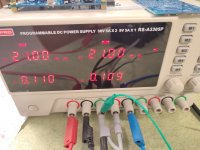
i just let run at idle current of 106mA / 21V rail since 6 hours and wverything is fine. DC offset is about -33mV. i let run the scope to look at some graphs.
current is now stable also the DC offset is not ideal but stable.
no heat - everything is less then luke warm 😉
kr
chris
i just let run at idle current of 106mA / 21V rail since 6 hours and wverything is fine. DC offset is about -33mV. i let run the scope to look at some graphs.
current is now stable also the DC offset is not ideal but stable.
no heat - everything is less then luke warm 😉
kr
chris
Attachments
hi
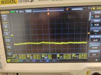
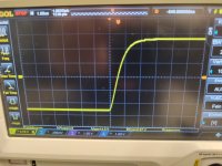
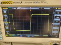
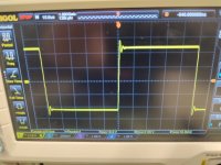
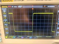
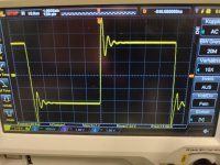
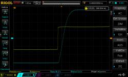
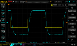
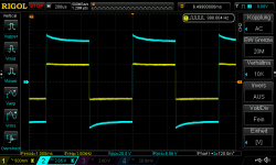
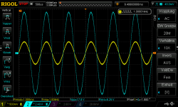
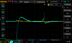
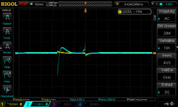
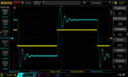
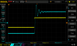
here is a first test with 9R and just to small 5W/18R resistors parallel.
this amp is stable with 10kHZ and 100nf and 390nF at about 5WATT
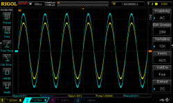
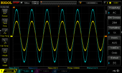
sine wave i test is done with about 7,4WATT and the upper fg was with 9R load 280Khz
not bad 😉
kr
chris
here is a first test with 9R and just to small 5W/18R resistors parallel.
this amp is stable with 10kHZ and 100nf and 390nF at about 5WATT
sine wave i test is done with about 7,4WATT and the upper fg was with 9R load 280Khz
not bad 😉
kr
chris
Attachments
-
 square_20kHz_about 6 WATT into 9R_slew rate.jpg373.3 KB · Views: 29
 -
 square_20kHz_about 6 WATT into 9R.jpg424.6 KB · Views: 37
 -
 square_10kHz_about 6 WATT into 9R_with 120nF.jpg352.7 KB · Views: 35
 -
 square_10kHz_about 6 WATT into 9R.jpg382.7 KB · Views: 36
 -
 square_10kHz_about 6 WATT into 9R with 390nF.jpg403.3 KB · Views: 32
Hi
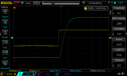
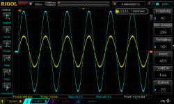
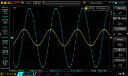
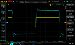
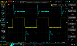
here are some measurments with my smal load resistor. the values can be read in the filename
here are some measurments with my smal load resistor. the values can be read in the filename
Attachments
-
 LCH_9R_17,66W_1Khz_square_slewrate.png36.7 KB · Views: 31
 -
 LCH_9R_17,66W_1Khz_square.png43.6 KB · Views: 30
 -
 LCH_9R_9W_70Khz_square.png43.1 KB · Views: 33
 -
 LCH_9R_9W_20Khz_square_slewrate.png37 KB · Views: 29
 -
 LCH_9R_9W_20Khz_square.png44.6 KB · Views: 31
 -
 LCH_9R_9W_10Khz_square_slewrate.png36.8 KB · Views: 30
 -
 LCH_9R_9W_10Khz_square.png42.1 KB · Views: 34
 -
 LCH_9R_9W_1Khz_square_slewrate.png36.8 KB · Views: 28
 -
 LCH_9R_9W_1Khz_square.png42.8 KB · Views: 34
 -
 LCH_9R_8_66W_1Khz_sine.png57.8 KB · Views: 26
 -
 LCH_9R_5W_fg_upper_300Khz_sine.png50.7 KB · Views: 34
 -
 LCH_9R_5W_fg_lower_3hz_sine.png50.4 KB · Views: 30
 -
 LCH_9R_5W_1Khz_sine.png55.2 KB · Views: 34
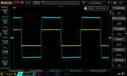
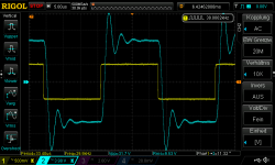
square wave at 9R and about 9WATT with cap load.
Attachments
-
 LCH_9R_120nF_20kHz_square.png43.1 KB · Views: 34
 -
 LCH_9R_120nF_10kHz_square.png44.8 KB · Views: 29
 -
 LCH_9R_120nF_30kHz_square.png44.9 KB · Views: 33
 -
 LCH_9R_220nF_10kHz_square.png44.9 KB · Views: 30
 -
 LCH_9R_220nF_20kHz_square.png47.3 KB · Views: 35
 -
 LCH_9R_330nF_30kHz_square.png47.4 KB · Views: 32
 -
 LCH_9R_220nF_30kHz_square.png46.8 KB · Views: 34
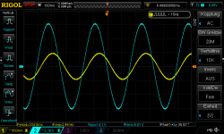
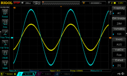
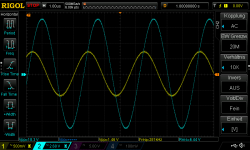
hi
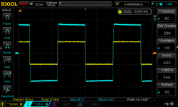
some measurements at 4R and 8R with my L channel.
still DC ofset with 21Vrail too high for my taste.
at home i´v got -48mvDC offset...
tests are fine.
some measurements at 4R and 8R with my L channel.
still DC ofset with 21Vrail too high for my taste.
at home i´v got -48mvDC offset...
tests are fine.
Attachments
-
 LCH_590Vrms input_4R_26,5W_1Khz_sine.png50.1 KB · Views: 35
 -
 LCH_500Vrms input_8R_9,85W_square_slewrate.png38 KB · Views: 38
 -
 LCH_500Vrms input_8R_9,85W_fg_upper_281kHz.png49.7 KB · Views: 33
 -
 LCH_500Vrms input_8R_9,85W_fg_low_3Hz.png51.9 KB · Views: 31
 -
 LCH_500Vrms input_8R_9,85W_220nF 20kHz.png43 KB · Views: 39
 -
 LCH_500Vrms input_8R_9,85W_220nF 10kHz.png38.7 KB · Views: 35
 -
 LCH_370Vrms input_4R_10,66W_fg_upper_250kHz.png48.4 KB · Views: 33
 -
 LCH_370Vrms input_4R_10,66W_1Khz_sine.png57.4 KB · Views: 35
 -
 LCH_690Vrms input_8R_18,6W_1Khz_sine.png56.6 KB · Views: 35
- Home
- Amplifiers
- Solid State
- JAT EZ amp - idea by John Audio Tech