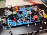
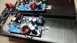
My bootstrap amp when powered the first time it shows -50mv dc offset. After matching the input ltps it instantly dropped to a steady -11mv. Not an ideally low measurement but it sure is an acceptable range. 🙂
the transistors at the input LTP are matched.
the topic is still the eays design of this amp. no current mirror...etc.
the topic is still the eays design of this amp. no current mirror...etc.

Usually what will cause any offset is the input differential.
Why I use 1% resistor for simplified amps.
Otherwise normal audio practice would be to try and match the input transistors.
And by default the board design should mount them flat to flat for any amplifier.
They should be thermally bonded flat to flat, little heat shrink to hold them together.
Same with mirrors should be thermally bonded.
Otherwise is interesting why diy audio doesnt see more designs with dual transistor packages
since they are thermally bonded in same package. And usually well matched/ laser trimmed.
Such as FMBM5551/5401 dual matched package

Old school was 2N6795 and many others in dual matched can/T0-78

Why I use 1% resistor for simplified amps.
Otherwise normal audio practice would be to try and match the input transistors.
And by default the board design should mount them flat to flat for any amplifier.
They should be thermally bonded flat to flat, little heat shrink to hold them together.
Same with mirrors should be thermally bonded.
Otherwise is interesting why diy audio doesnt see more designs with dual transistor packages
since they are thermally bonded in same package. And usually well matched/ laser trimmed.
Such as FMBM5551/5401 dual matched package
Old school was 2N6795 and many others in dual matched can/T0-78
yep...i do so....
i personally made my matching of TO92 like this.
warming lamp- so i get about 40°C and then match with DCA75pro and pres 4 time the test to get a last valid reading.
then VBE and HFE match.
chris
i personally made my matching of TO92 like this.
warming lamp- so i get about 40°C and then match with DCA75pro and pres 4 time the test to get a last valid reading.
then VBE and HFE match.
chris
Hi
the R channel is also in operation and shows the same.
gain 24,7dB andthe same fg high (4R 250kHz, 8R 280kHz) and fg low 3 Hz at 10WATT.
quiecent current is set to 120mA per rail.
the only thing i have to correct is the max power at 4R for both channels. i forgot to set the OCP higher at my PSU. now i get 11,7Vrms into 4R so it is about 34WATT.
Good eveneing,
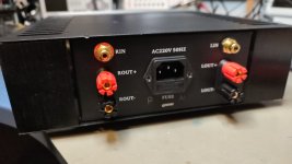
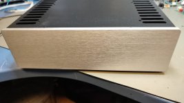
meanwile i build the amp in a very small housing with a SMPS by Aliexpress 24V +/- rail.
next step is the RCA connection..
have fun
chris
meanwile i build the amp in a very small housing with a SMPS by Aliexpress 24V +/- rail.
next step is the RCA connection..
have fun
chris
Attachments
-
 JAT EZamp_8.jpeg248.4 KB · Views: 67
 -
 JAT EZamp_7.jpeg269.3 KB · Views: 66
 -
 JAT EZamp_6.jpeg300.7 KB · Views: 61
 -
 JAT EZamp_5.jpeg140.8 KB · Views: 63
 -
 JAT EZamp_4.jpeg135.4 KB · Views: 59
 -
 JAT EZamp_3.jpeg179.1 KB · Views: 65
 -
 JAT EZamp_2.jpeg260.3 KB · Views: 73
 -
 JAT EZamp_1.jpeg269.7 KB · Views: 68
Hello
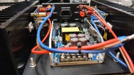
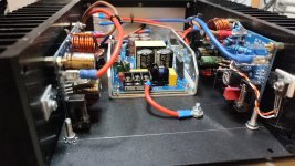
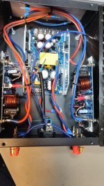
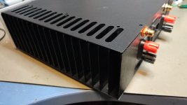
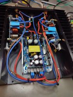
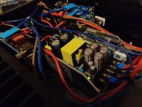
the amp is finished and sound check was okay. it is a compact housing and not much space inside.
here some pics
DC offset is 5mmV at L ch, 8mv at R CH- this is because thes chines SMPS has unsymmetrically voltages. -21,04V - 21,10V
but it is fine for me. power on/off is noticable but not too critical. at tswitch on i measure 42mV DC offset but after 2 minutes everything is fine.
sound check:
the amp sounds nice and if a have just a low level of noise at the speakers...fine.
the soundstage is small but the amp try the give you the illusion of a bigger amp (FX8 or FH9, VSQA), but the sound is not so wide and deep as i want to.
ever tone and harmonics are fine - no critic here. at easy titles it is relaxed and the lower end is impressive but if the track is a bit more complex the seperation is getting closer together. but do not forget it is a easy amp 😉 .
actually i do not have no SSR or Dc protection relay - so my boom boom tilte was loud without problems. i do not go more up with the volume. everything is fine - no heat at the heatsink.
funny amp -good sound but i have to compare to my LM1875/ UTC 20250 chipamps from 2017. from my memories it is better in presenting a better soundstage as the chipamp i have done.
kr
chris
Attachments

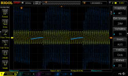
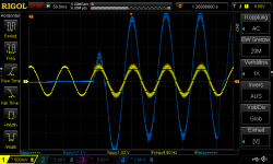
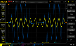
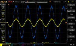
The SMPS from Aliexpress is not so fine during test, why i will explain to you.
i have no problems during listening but the behavior is strange. i explain:
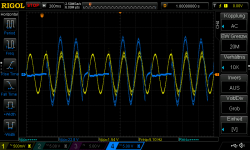
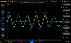
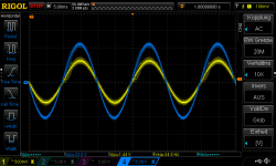
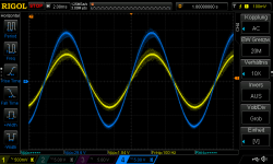
i want to check the upper and lower fg and i found a hick up mode at the SMPS at low frequencies.. hick up mod at a SMPS means a kind of OCP -over current protection - and the SMPS shuts shortly down - check if the "short" is gone - want to try again and goes again in the hick up mode.
yellow input signal
blue output signal at the LS connectors
i have no problems during listening but the behavior is strange. i explain:
i want to check the upper and lower fg and i found a hick up mode at the SMPS at low frequencies.. hick up mod at a SMPS means a kind of OCP -over current protection - and the SMPS shuts shortly down - check if the "short" is gone - want to try again and goes again in the hick up mode.
yellow input signal
blue output signal at the LS connectors
Attachments
-
 Hickup mode at 4R_5Hz_16WATT_1.png57.7 KB · Views: 24
 -
 Hickup mode at 4R_5Hz_16WATT_2.png49.4 KB · Views: 29
 -
 Hickup mode at 4R_20Hz_6.5WATT_1.png86.3 KB · Views: 31
 -
 Hickup mode at 4R_10Hz_9WATT_2.png57.9 KB · Views: 29
 -
 Hickup mode at 4R_10Hz_9WATT_1.png66.6 KB · Views: 25
 -
 Hickup mode at 4R_20Hz_6.5WATT_2.png59.5 KB · Views: 35
 -
 Hickup mode at 4R_50Hz_16,5WATT_1.png54.3 KB · Views: 30
 -
 Hickup mode at 4R_100Hz_27WATT_1.png55.9 KB · Views: 26
Last edited:
Hi
to close the phase 1 with darlington BDW93/94C and a lot of help from WD and Minek and for sure Peter (KICAD) -thanks again.
here my last LTspice file.
i changed the VAS from BD139 to the 2N5550 at the database i am too lazy to implement the 2N5551 (in real amp).
i re-check the power dissapation of this little guy (To92) with a current of max 8ma and a voltage swing of about 38Vp i got just more then 300mW -so its okay if you do not push hours hard. i use a heatsink on this transistor.
for a version 2 of this amp - my ideas:

have fun
chris
to close the phase 1 with darlington BDW93/94C and a lot of help from WD and Minek and for sure Peter (KICAD) -thanks again.
here my last LTspice file.
i changed the VAS from BD139 to the 2N5550 at the database i am too lazy to implement the 2N5551 (in real amp).
i re-check the power dissapation of this little guy (To92) with a current of max 8ma and a voltage swing of about 38Vp i got just more then 300mW -so its okay if you do not push hours hard. i use a heatsink on this transistor.
for a version 2 of this amp - my ideas:
- all values updated -like my real amp
- caps should be marked with + at the mask
- C4 is bipolar -22µF i used (mooly amp), my
- use isolated TO-126 TTC004BQ as Q4 to be save about isolation with ouput transistor
- R20 VAS Q5 is now 20R to get 6mVDC offset - it dependas on your rail voltage and LTP matching and idle current
- delete CFB1+CFB2
- add a bigger ouput transitor like the 2SD2390 (old Darlingtons in TO3P housing vom Denon AVR)
- ouput transistor is like WD wrote - a lot of possiblities - MJE15028, DV44HV, or any other cheap one
chris
Attachments
Last edited:
sound check:
i compare with my UTC2050 chip amp in the "normal" schoolies amp configuration in the year 2017 i guess.
the EZ amp sound better. more relaxing sound then the chip amp and give me the feeling of a"bigger" amp like the FX8,FH9, VSQA but not so dynamic like they can handle the music.
and yes with my configuration i can play loud...really loud without problems. (SMPS)
try it - its realy nice amp
chris
John Audio Tech get his amp running
here is the final version which is stable and at the 30V rail on the audio analyser.
EZ amp with 30v + QA403
the previous video where he gets it working :
EZ amp is not burn
here is the final version which is stable and at the 30V rail on the audio analyser.
EZ amp with 30v + QA403
the previous video where he gets it working :
EZ amp is not burn
- Home
- Amplifiers
- Solid State
- JAT EZ amp - idea by John Audio Tech