BOM made by the LT spice schematic.
Q5 is in my "guestimation" partly critical. the swing is more then 38Vp and the current 10mA --> so we have 380mW. this happens just at max power!
so i keep T092 as VAS transistor Q5 at this moment. if you pus often loud and long then the heatsink at post #18 is needed. or you can stik with thermal past and cable strip a cent coin on it.
have fun
chris
Attachments
good day,
i am sorry i totally forget to keep the CCS at about 2mA, DC offset change of R6 and after the square wave test with 8R and 440nF i have to change c11 miller cap at Q5 to 150pF.
look at the log file at the max power! THD 0,025%
i know that is simulated but its better then i dreamed 😉
for me it is now finished.
lets do KICAD!
kr
chris
Attachments

What pcp software you use?, you are fast
VBE transistor Q4 would share same heatsink as power transistor for thermal tracking.
Usually for low distortion and SOA we try for a cooler Vas transistor. 6 to 8ma
But yes with Darlington outputs Vas is driving them directly so often you see 8 to 10ma to effectively drive them at high frequency.
You can get good idea of needed Vas current to drive BD93/94 by driving square wave input signal at amp input 100 to 400mv
And see how well power transistor turn on time is at 10 kHz to 20 kHz with 4 ohm load . If slew is bad at 6ma to 8ma then yes 9ma to 10ma is needed.
Okay...will check.
The lt Spice was supported by minek. If i had troubles with AA14 amp. Minek support me really well. The lt Spice configuration was done by him.
Just start with short Input....bias and DC Offset
Then use v4... Sine Wave.
Square is done with v3
The lt Spice was supported by minek. If i had troubles with AA14 amp. Minek support me really well. The lt Spice configuration was done by him.
Just start with short Input....bias and DC Offset
Then use v4... Sine Wave.
Square is done with v3
What pcp software you use?, you are fast
VBE transistor Q4 would share same heatsink as power transistor for thermal tracking.
Usually for low distortion and SOA we try for a cooler Vas transistor. 6 to 8ma
But yes with Darlington outputs Vas is driving them directly so often you see 8 to 10ma to effectively drive them at high frequency.
You can get good idea of needed Vas current to drive BD93/94 by driving square wave input signal at amp input 100 to 400mv
And see how well power transistor turn on time is at 10 kHz to 20 kHz with 4 ohm load . If slew is bad at 6ma to 8ma then yes 9ma to 10ma is needed.
Hi whitedragon
pc software is kicad 8.08. and the kicad was since beginnen preset. i am not fast.
first layout with Q4 near Q6 bring me in trouble with the layout. so i decided to do like VSQA amp- at the layout it is i bit away but in real i will use 3 wires and mount the VAS Q4 to the Q6.
i generat a puls generator with 10kHZ and set the signal to 0,4V
with my setup i got with 10kHz just 3,4V/µSec is that good?
with setting the bias of vas up to about 14mA i just got 4,1V/µsec. from JAT video and in the forum i realized that darlingtons are slow because of there internal resistors and it is not easy to speed them up.
so what is an exeptable slew rat for such a amp?
about Q5---> if more bias in VAS is needed then it is clear that Q5 must be a TO126 transistor!
kr
chris
Last edited:
my little knowledge is really low level.
my new Bob cordell book should give me more ideas. in amp pic 3.1 it is the VAS biased with a CCS.
i just try shortly to push the input differaential pair with more CCS current..about 3,5mA...i just got 4,6V/µsec 🙄
my guestimation is with that "easy" configuration it is needed to set CCS of the diff pair much higher to "load" the current for the VAS transistor Q5.
right?
ps: it is really intensive...i will dream about LTspice,CCS... 😆 😆 😆 😆 😆
kr
chris
in Bob cordells book it is written (page 9, 60..)that a low performance amp with about 10W has normaly about 5V/µsec slew rate. high performance amps with bigger voltage swing must have better slew rat...logical. EG 100W must have 50-300V/µsec. bigger voltage swing must be faster...logical...
so it is okay for the easy amp.
so it is okay for the easy amp.
good morning
for measurements of the amp without thiele network at the output i got better measurements. 2,3V/µsec better. 6,3V/µsec

as written in bob cordell - the input HF filter could also be omitted, so i disconnect the input C2 220pF. it is a bitt better 6,628V/µsec

for measurements of the amp without thiele network at the output i got better measurements. 2,3V/µsec better. 6,3V/µsec
as written in bob cordell - the input HF filter could also be omitted, so i disconnect the input C2 220pF. it is a bitt better 6,628V/µsec
Hy again
after reading bob cordell -chapter 3 with degeneration resistors to reduce huge 20kHz THD i decided to do so. AT JAT EZ amp is a different amp then bob once because the degeneration resistors at the input stage was done at the beginning but no Re at the VAS transistor Q5! so i implement this. the result is that the miller cap at Q5 can be reduced - 27p (maybe higher at the real amp ...47p...68p) EZ amp is still a bootstrapped version. i keep that.
i tried different inductances a changed to 1µH to squeeze out a bit the slew rate 😉
DC offset is about 1-2mV. bias current CCS is up to 2,4mA , VAS current is about 10,14mA to have a better slew rate for 20kHz square.
simulations LT spice give:
load 8R -440nF cap
20kHz square test: slew rate without zobel netwerk -Out woZ= 7V/µsec, after about 3V/µsec
1kHz square test: slew rate without zobel netwerk -Out woZ= 16V/µsec, after about 5,72V/µsec
load 4R -440nF cap
20kHz square test: slew rate without zobel netwerk -Out woZ= 7V/µsec, after about 2,8V/µsec
1kHz square test: slew rate without zobel netwerk -Out woZ= 15,9V/µsec, after about 5,51V/µsec
THD 4R at max power = 0,0959%...17,66WATT
THD 8R at max power = 0,0417%...35WATT
THD 4R at max power = 0,0587%...19WATT
THD 8R at max power = 0,0288%..9,6WATT
THD 4R at max power = 0,0237%...2,44WATT
THD 8R at max power = 0,014%.....1,2WATT
here is the setup for a pulse generator for 20kHZ:

schematic

that will be the version to go.
have fun
chris
after reading bob cordell -chapter 3 with degeneration resistors to reduce huge 20kHz THD i decided to do so. AT JAT EZ amp is a different amp then bob once because the degeneration resistors at the input stage was done at the beginning but no Re at the VAS transistor Q5! so i implement this. the result is that the miller cap at Q5 can be reduced - 27p (maybe higher at the real amp ...47p...68p) EZ amp is still a bootstrapped version. i keep that.
i tried different inductances a changed to 1µH to squeeze out a bit the slew rate 😉
DC offset is about 1-2mV. bias current CCS is up to 2,4mA , VAS current is about 10,14mA to have a better slew rate for 20kHz square.
simulations LT spice give:
load 8R -440nF cap
20kHz square test: slew rate without zobel netwerk -Out woZ= 7V/µsec, after about 3V/µsec
1kHz square test: slew rate without zobel netwerk -Out woZ= 16V/µsec, after about 5,72V/µsec
load 4R -440nF cap
20kHz square test: slew rate without zobel netwerk -Out woZ= 7V/µsec, after about 2,8V/µsec
1kHz square test: slew rate without zobel netwerk -Out woZ= 15,9V/µsec, after about 5,51V/µsec
THD 4R at max power = 0,0959%...17,66WATT
THD 8R at max power = 0,0417%...35WATT
THD 4R at max power = 0,0587%...19WATT
THD 8R at max power = 0,0288%..9,6WATT
THD 4R at max power = 0,0237%...2,44WATT
THD 8R at max power = 0,014%.....1,2WATT
here is the setup for a pulse generator for 20kHZ:
schematic
that will be the version to go.
have fun
chris
Attachments
id would be nice to help me to configure LTspice that i can have alog file with 10kHz upt to 20kHZ datas-THD
thx
chris
thx
chris
good morning
in post 31 is a very heavy capcitive load to check the capability of current and slew rate. 400nF is a LS cable real not realistic.
i choose a 3m cable with 100pF/m (e.g.. mogami 3103 or something else). so the cap. load is 300pF.
THD looks the same...okay?!
the max slew rate is not much better before zobel filter compared to post 31 i guess that is the max what the amp can do.
but after that ...yes...marked bolt
load 8R - 300pF cap
20kHz square test: slew rate without zobel netwerk -Out woZ= 7,15V/µsec, after about 6,3/µsec
1kHz square test: slew rate without zobel netwerk -Out woZ= 16,38V/µsec, after about 13,7V/µsec
load 4R - 300pF cap
20kHz square test: slew rate without zobel netwerk -Out woZ= 7,12V/µsec, after about 5,55/µsec
1kHz square test: slew rate without zobel netwerk -Out woZ= 16,38V/µsec, after about 11,95V/µsec
Last edited:
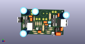
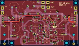
KICAD first try...my template was the perfect PCB by prasi for the FH9 amp.
if you find something to do better then please give me feedback.
thx

F CU

B cu


if you find something to do better then please give me feedback.
thx
F CU
B cu
Last edited:
Dear Peter,
your are my friend. yesterday evening i ask for a short look up and now its ready! your are amazing. the pcb is finished!.
THANK you!
to all others:
please feel free and build that amp and give me feedback.
kr
chris
your are my friend. yesterday evening i ask for a short look up and now its ready! your are amazing. the pcb is finished!.
THANK you!
to all others:
please feel free and build that amp and give me feedback.
kr
chris
- Home
- Amplifiers
- Solid State
- JAT EZ amp - idea by John Audio Tech