Oh man, I was proud of that regulator.
Let me defend it for one more round before I pull the plug.
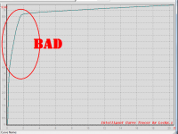
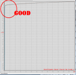
I get a 100hZ ripple (from the rectifiers) of < 4uV, and a 20kHz ripple (from the varying load) of 57uV. Both those seem well beyond what is required, but perhaps SPICE isn't telling me the whole story?
This probably has me most worried. "Major pain" can be OK if I have the tools (intellectual and otherwise) to debug it, which isn't necessarily a given at this point.
Cheers,
Jeff.
Let me defend it for one more round before I pull the plug.
Would I see this in SPICE? My model has the regulator feeding a current sink that draws 83mA +/- 4.5mA (at 20kHz).Jeff,
1) To correctly implement a shunt in this application requires a current source. Otherwise ripple can sometimes be an issue.
I get a 100hZ ripple (from the rectifiers) of < 4uV, and a 20kHz ripple (from the varying load) of 57uV. Both those seem well beyond what is required, but perhaps SPICE isn't telling me the whole story?
Yep, it's currently running at a no-load quiescent current of 118mA. The heatsink is spec'ed to allow the MOSFET to survive that, but the front-end's class A bias eats a lot of that which reduces the "normal" quiescent shunt current to 35mA.2) To get a shunt to work optimally you need to dissipate as much current through the shunt element as the circuit draws. In this case almost 100 mils. across 55 V.Otherwise the shunt will sound weird or drop out of regulation on peaks.
Yeah, I started out with just a Zener controlling the shunt, but I got goaded into doing something "better". 😀3) The op-amp chosen has a high degree of influence on the sound. I also limits your ability to change it's characteristics (think black box). Same issue with the TL431.
4) The regulator in this application does not need to be as complex as that used in a pre-amp, for example, because of the signal levels involved.
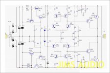
Don't get me wrong, a shunt regulator can be one of the best at the expense of complexity and heat dissipation. I built a prototype pre-amp that used a shunt and it was a major pain getting it right. I will share photos later if requested. The regulator ended being as complicated as the gain circuit and more in a later iterations.
This probably has me most worried. "Major pain" can be OK if I have the tools (intellectual and otherwise) to debug it, which isn't necessarily a given at this point.
Cheers,
Jeff.
FWIW, my "poor man's" current source (the 3 resistors) is dropping about 13V with a power dissipation of about 1.7W.
Jeff,
Everything looks good but I beg your indulgence on one item, the regulator.
2) To get a shunt to work optimally you need to dissipate as much current through the shunt element as the circuit draws. In this case almost 100 mils. across 55 V.
Jam
I generally go with at least double or even triple the quiescent current draw of the circuit through the shunt, depending on dissipation requirements.
Jeff,
Everything looks good but I beg your indulgence on one item, the regulator.
1) To correctly implement a shunt in this application requires a current source. Otherwise ripple can sometimes be an issue.
Jam
A passive current source consisting of RCRCRC usually gives better filtering than a simple transistor based ccs. Either way it’s plenty good enough.
Maybe give an example of how this might occur.
Maybe the semiconductor ccs works better with AC mains fluctuation.
Last edited:
I read the Waagbo article again (that's one I had read before), and did note that my resistor CS is much bigger (110R vs 27R) than the one he was using in his simple shunt. FWIW....
Trying it both ways is probably the only way to know.
Jeff
You could easily add both current source options on the pcb ie both passive and transistor current sources.
Jeff
You could easily add both current source options on the pcb ie both passive and transistor current sources.
Last edited:
If you would consider discrete options we can work through something simple.
Absolutely. "Discrete" tickles my do-it-yourself fancy. (Well, at least until I get a fab line to do my own opamps.... 😀)
I assume a 2-stage would be sufficient? In other words, a simple BJT LTP directly driving the shunting MOSFET?
Even a single gain stage driving the shunt maybe more than adequate.
At least start simple and only add gain stages where necessary.
We can look at something very basic to start with and see if that is adequate.
Anything better than 70 dB psrr and 10mOhms output impedance, should be adequate and achievable with a simple circuit.
Or we can consider other options.
For me all that matters is psrr, output impedance, and simplicity.
I like it as simple as possible.
Last edited:
My CRCRC opamp version was 130dB / 4mOhms. But I'm willing to sacrifice some performance for something that won't be squirrelly.
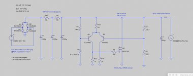
Here's my first shot across the bow. Performance isn't great yet (oddly it's better at high frequency than low).
Ignore the big TO-247. I didn't want to go digging up my IRF610 spice model....

Here's my first shot across the bow. Performance isn't great yet (oddly it's better at high frequency than low).
Ignore the big TO-247. I didn't want to go digging up my IRF610 spice model....
Attachments
Just went for coffee with Mark W and look what happens...
Seriously guys I have built many shunt regulators and current and heat are the key. If you look at the original Stax designs you will see what I mean. That is why most modern designs shy away from shunts because of the complexity and heat dissipation requirements. In my pre-amp I run twice as much current through the shunt than the actual circuit, makes the whole chassis toasty. Pico uses more than that...😱
Sometimes a zener controlling the shunt (done correctly) sounds better. hint. response time, over shoot and how do you make the zener quieter.
Dissipation 100 mils. over 50 volts( shunt element) plus dissipation volt drop across resistor/ current source 200 to 300 mils. for best operation not forget that compounding the issue is you need a reasonable volt drop across the regulator for best operation.....no fun.
Last edited:
I agree with Jam.
I am getting excellent results with series regulation without the ridiculous amounts of heat.
I am getting excellent results with series regulation without the ridiculous amounts of heat.
My CRCRC opamp version was 130dB / 4mOhms. But I'm willing to sacrifice some performance for something that won't be squirrelly.
[/IMG]
The audible difference between a power supply of 70dB reduction and 130dB reduction used to power a front end power amp circuit that will probably have a psrr better than 70dB will be inaudible.
The biggest Audible difference will be the differences in output impedance of the power supply, that's my opinion though.

I've always liked John Curl's idea to use two voltage regulators in series. First is an LM317 series-pass voltage regulator, whose purpose is to "knock down the ripple" as John puts it. Ripple attenuation is -66dB, so 3V of peak-to-peak ripple at the input, becomes 1.5 millivolts of peak-to-peak ripple at the LM317 output. After that comes a shunt regulator, whose job is to provide a low output impedance from DC to the 9th harmonic of 20 kHz.
Notice that a shunt regulator draws a constant current from its input. Which in JC's arrangement means, the LM317 regulator sees a constant current load (the shunt regulator). Constant voltage and constant current. What a pleasant situation!
Yes, there is a larger voltage drop across the two regulators in series. About 3V for the LM317, plus another 3xVBE (~ 2.4V) for the shunt regulator, if you build a low-headroom current source {or an Ed Simon resistor!} using a BJT whose Ice-Vce curves are nice and flat at low Vce. In my opinion, 5.4V of drop is a small price to pay for spectacular performance.
Bob Cordell's book remarks that it's pretty easy to add your own extra winding(s) on a toroidal power transformer, to get boosted rail voltages for the low current (sub 200mA) stages of a power amp. In a preamp, where a 50VA transformer is ridiculously too big, you simply buy a different transformer. Same price, more volts, fewer amps, same VA rating.
_
Attachments
I've always liked John Curl's idea to use two voltage regulators in series. First is an LM317 series-pass voltage regulator'
After that comes a shunt regulator, whose job is to provide a low output impedance from DC to the 9th harmonic of 20 kHz.
_
I agree that this is a good idea
- Home
- Amplifiers
- Pass Labs
- JamJar: an HPA-1-inspired power amp