Oscillating might have been the wrong term. It's very chaotic.
Interestingly, if I switch to LTSpice's alternate solver, it's very slow but I don't get any outbursts....
Might need to try a discrete Darlington....
Interestingly, if I switch to LTSpice's alternate solver, it's very slow but I don't get any outbursts....
Might need to try a discrete Darlington....
I wouldn't let dodgey Spice behavior necessarily rule out an otherwise decent circuit. It is very easy to get trapped into paralysis by analysis. Been there, done that.
Another idea which may be going out on a limb would be to use an existing discrete regulator for the front end. I've used the AMB Sigma 22 for DIY versions of a Naim Dual HiCap DR and an XPS DR for my Naim preamp and CD player. The AMB designs work quite well, and don't take up too much space.
The power section of the supply might be well served by the latest LT4320 quad capacitor PSU being offered by Prasi on the Group Buy pages. I had a small amount of input into that board design. Mark Johnson has also contributed an idea for a Cap Multiplier to be inserted between the first and second stages of capacitance. This is something that I recommend, and will be using on the next big amp that I build from scratch.
Itsme,
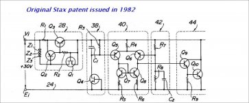
Historically the use of shunt regulators in audio goes back to Stax of Japan (an audio company way ahead of it's time). I can't find my copy of the original patent, but here is a copy of the patent schematic........Shunts have the capability of being some of the best regulators as long as you understand their complexity and heat dissipation.
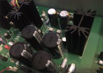
I have worked on a shunt for a prototype pre-amp (picture attached)...and this is for only one channel at 180 mils. draw at 24V and heat sink temp 55deg C and is not the final version which is more complex.😱
Jam
Historically the use of shunt regulators in audio goes back to Stax of Japan (an audio company way ahead of it's time). I can't find my copy of the original patent, but here is a copy of the patent schematic........Shunts have the capability of being some of the best regulators as long as you understand their complexity and heat dissipation.
I have worked on a shunt for a prototype pre-amp (picture attached)...and this is for only one channel at 180 mils. draw at 24V and heat sink temp 55deg C and is not the final version which is more complex.😱
Jam
Attachments

Last edited:
Sometimes you have to walk the road on your own (even when you've been told where it leads).
So what did I learn?
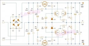
If you want to get away with no series pre-reg (and still use Aavid 529 heatsinks) then you have to size the resistors for a particular transformer regulation and a particular mains nominal voltage (allowing for an 5% swing in either direction).
Otherwise you need a pre-reg.
In the end, "as simple as possible but no simpler" turns out to be not that simple. On the other hand, I was able to avoid the current mirror, and it still manages excellent performance without the complexity of some "audio spec" regulators.
But yeah, "this is a knoiff."

(Ignore the shorted rectifier. The last thing I did before taking the screen capture was a small-signal analysis to get the attenuation figures.)
Cheers,
Jeff.
So what did I learn?
If you want to get away with no series pre-reg (and still use Aavid 529 heatsinks) then you have to size the resistors for a particular transformer regulation and a particular mains nominal voltage (allowing for an 5% swing in either direction).
Otherwise you need a pre-reg.
In the end, "as simple as possible but no simpler" turns out to be not that simple. On the other hand, I was able to avoid the current mirror, and it still manages excellent performance without the complexity of some "audio spec" regulators.
But yeah, "this is a knoiff."
(Ignore the shorted rectifier. The last thing I did before taking the screen capture was a small-signal analysis to get the attenuation figures.)
Cheers,
Jeff.
Attachments
If you want to get away with no series pre-reg (and still use Aavid 529 heatsinks) then you have to size the resistors for a particular transformer regulation and a particular mains nominal voltage (allowing for an 5% swing in either direction).
Jeff.
I allow for 15% mains fluctuation
Jeff,
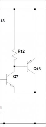
Regulator is looking good ...I would use a cap across D4 and D9 to further reduce noise. I would also slow down the turn on of the pre-regulator (good thing) if it is large enough.
I would also try a darlington for Q7 or mosfet if you candle the drop.
I will also agree with pico about a 15% mains swing 10% being the bare minimum.
Jam
Last edited:

I think in this case Jeff is using the resistor in place of a current source/limiter which is valid but not optimum. The pre-regulator sets a fixed drop across R6 and Ohms Law does the rest.
Jam
Jam
Last edited:
Stax of Japan
Thank you Jam, haven't seen that one before, I did have a copy of a Stax HV shunt, I lost it when my old PC's PSU fried everything.
I was converted to shunts many years ago when I built the Borbely All FET Shunt.
Attachments
I allow for 15% mains fluctuation
15% total, or +/-15%?
(The one posted above is good for 68 - 90V, so 32% total for mains fluctuation, regulation, etc.)
Jeff,
Regulator is looking good ...I would use a cap across D4 and D9 to further reduce noise. I would also slow down the turn on of the pre-regulator (good thing) if it is large enough.
I would also try a darlington for Q7 or mosfet if you candle the drop.
I will also agree with pico about a 15% mains swing 10% being the bare minimum.
Jam
Yeah, SPICE doesn't seem to model zener noise so I only put the bypass caps in when I move the schematic to Kicad.
I didn't actually try any other options for the pre-regulator as it "worked out of the box" (unlike most everything else). 😀
Series regulator on the way. I think I can get it to the same specs with 1/2 the parts....
Cheers,
Jeff.
I think in this case Jeff is using the resistor in place of a current source/limiter which is valid but not optimum. The pre-regulator sets a fixed drop across R6 and Ohms Law does the rest.
Jam
Yeah, I always start out with a resistor for a CS and then move to something more sophisticated if required.
The first couple of designs I built were valve amplifiers, where this seems to be more common....
Cheers,
Jeff.
I think pico might mean +/- 15 V % That is actually what I used in the HPA-1,
but it all depends on your local power. I usually find huge swings in summer at my location but better safe than sorry.😉
Jam
but it all depends on your local power. I usually find huge swings in summer at my location but better safe than sorry.😉
Jam
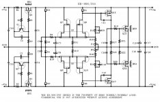
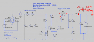
Here's the series version. It's beaten by the shunt (spec-wise) only in low-frequency attenuation.
I tried a current mirror in the diff, a current source in the tail, and a couple of other things, but none of them seem to affect the low-frequency.
Any pointers appreciated.

PS: Ignore R1; it's just handling the baseline 72mA of current draw. SPICE doesn't like having it in the current source in this topology for some reason.
I tried a current mirror in the diff, a current source in the tail, and a couple of other things, but none of them seem to affect the low-frequency.
Any pointers appreciated.
PS: Ignore R1; it's just handling the baseline 72mA of current draw. SPICE doesn't like having it in the current source in this topology for some reason.
Attachments
Since your series pass transistor is operated as a common source amplifier, it contributes its own voltage gain greater than unity. And now you have a two stage amplifier cascade whose "frequency compensation" is determined in large part by the ESL, ESR, and capacitance of the capacitors connected to the voltage regulator's output. But there are no capacitors present on that schematic attached to #617, and so I fear you might not have thoroughly explored the worst cases of (in)stability without them.
_
_
Attachments
- Home
- Amplifiers
- Pass Labs
- JamJar: an HPA-1-inspired power amp