Son of JamJar....
This wont be a commercial product........it will be designed with the spirit of this thread and the design will be in a different thread in the forum.
..but we will have to wait till Jeff's design is built and tested.😉
Jam
This wont be a commercial product........it will be designed with the spirit of this thread and the design will be in a different thread in the forum.
..but we will have to wait till Jeff's design is built and tested.😉
Jam
Last edited:
I've retired the SixPack and BuzzBomb names since both have lost the properties from whence their names originated (SixPack now has 12 output pairs and BuzzBomb now has reasonable stability and short-circuit survivability).
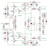
I've also modified the Hitachi schematic so that it contains values for driving either laterals or verticals. This allows one to build 4 different front ends to drive a set of dual-mode output boards -- or one could just choose a single front-end topology and and a single output stage and build that.
Jam Jar 'KISS' Vertical Driver
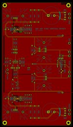
Jam Jar 'CFA' Lateral Driver
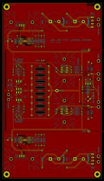
Jam Jar 'Hitachi' Front End
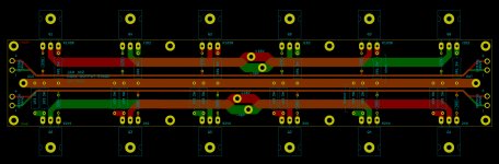
Jam Jar Dual Output Stage
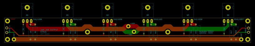
Jam Jar Output Stage
Schematics in PDF; layouts in JPG.
Cheers,
Jeff.
I've also modified the Hitachi schematic so that it contains values for driving either laterals or verticals. This allows one to build 4 different front ends to drive a set of dual-mode output boards -- or one could just choose a single front-end topology and and a single output stage and build that.
Jam Jar 'KISS' Vertical Driver
Jam Jar 'CFA' Lateral Driver
Jam Jar 'Hitachi' Front End
Jam Jar Dual Output Stage
Jam Jar Output Stage
Schematics in PDF; layouts in JPG.
Cheers,
Jeff.
Attachments
-
JamJarKISS.pdf140 KB · Views: 180
-
 JamJarDualOS.JPG300.7 KB · Views: 264
 -
 JamJarHitachi.JPG307.8 KB · Views: 268
 -
 JamJarCFA.JPG295.8 KB · Views: 254
 -
 JamJarKISS.JPG250.9 KB · Views: 268
 -
JamJarOS.pdf91.4 KB · Views: 168
-
JamJarHitachi.pdf178 KB · Views: 171
-
JamJarCFA.pdf160.3 KB · Views: 190
-
 JamJarOS.jpg169.4 KB · Views: 263
You said folded cascode...
First idea, maybe something like this? Ignore the O/P.
Attachments
I can't comment on the actual question, but if you put the capacitor in parallel with the resistor on your front-end cascodes I think you'd also want base stoppers for the cascode transistors.
Personally I like simple and leave out both. 😉
Personally I like simple and leave out both. 😉
...I think you'd also want base stoppers...
I was thinking along the lines of a capacitance multiplier, if the trannies go poof, I'll add some base resistors 🙂
You said folded cascode.............you should see the pre-amp I am designing for use with this power amp....hopefully I can get pico to contribute his regulator.😀
Jam
I will put forward a few design ideas with specs and you can decide which one you like, or suggest making changes.
I can put forward some unregulated capacitance multipliers that have very good specs as well.
Jam Jar Dual Output Stage
Jam Jar Output Stage
Schematics in PDF; layouts in JPG.
Cheers,
Jeff.
Hi Jeff
1) Lateral Mosfets have a pin out configuration of GSD, not the regular pin out of GDS.
2) I think it’s best that any driver stage that is used is also installed on the output boards like Jam suggested and also like on F4.
Last edited:
Yikes. So indeed. Sort of puts paid to the universal output stage board....1) Lateral Mosfets have a pin out configuration of GSD, not the regular pin out of GDS.
2) I think it’s best that any driver stage that is used is also installed on the output boards like Jam suggested and also like on F4.
I'm resisting this. If I put the drivers on the output board then I need an output board design per front-end (which makes them more expensive, and means I can't just mount a set of each drivers and swap front-ends in and out).
I'm resisting this. If I put the drivers on the output board then I need an output board design per front-end (which makes them more expensive, and means I can't just mount a set of each drivers and swap front-ends in and out).
No problem.
Yikes. So indeed. Sort of puts paid to the universal output stage board....
I think you could make it work with jumpers.
If you want some ideas I could draw it on paper.
That's a great idea -- but why not use the resistors as jumpers? Populate one set of resistor holes for verticals, and another for laterals (fortunately the gates don't move).
I think this might be over KiCad's head, though, so I'd have to go without DRC. 😉
I think this might be over KiCad's head, though, so I'd have to go without DRC. 😉
Itsme,
Not quite. It will not be a complementary circuit. The input will be a differential like Jeff"s circuit. to keep with the spirit of the current design.
Jam
Not quite. It will not be a complementary circuit. The input will be a differential like Jeff"s circuit. to keep with the spirit of the current design.
Jam
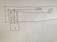
Lateral configuration with jumpers.
I didn’t label the jumpers hope it is obvious where the jumper wires are.
I can label if you need, or draw blank pcb without any jumpers inserted so it is clear.
I didn’t label the jumpers hope it is obvious where the jumper wires are.
I can label if you need, or draw blank pcb without any jumpers inserted so it is clear.
Attachments
Last edited:
Itsme,
Not quite. It will not be a complementary circuit. The input will be a differential like Jeff"s circuit. to keep with the spirit of the current design.
Jam
Sweet! (And we've already got the DIY HPA-1 circuit to go with JamJar 'CFA'.)
Jeff,
Everything looks good but I beg your indulgence on one item, the regulator.
1) To correctly implement a shunt in this application requires a current source. Otherwise ripple can sometimes be an issue.
2) To get a shunt to work optimally you need to dissipate as much current through the shunt element as the circuit draws. In this case almost 100 mils. across 55 V. Otherwise the shunt will sound weird or drop out of regulation on peaks.
3) The op-amp chosen has a high degree of influence on the sound. I also limits your ability to change it's characteristics (think black box). Same issue with the TL431.
4) The regulator in this application does not need to be as complex as that used in a pre-amp, for example, because of the signal levels involved.
Don't get me wrong, a shunt regulator can be one of the best at the expense of complexity and heat dissipation. I built a prototype pre-amp that used a shunt and it was a major pain getting it right. I will share photos later if requested. The regulator ended being as complicated as the gain circuit and more in a later iterations.
Just some thoughts.
Jam
Everything looks good but I beg your indulgence on one item, the regulator.
1) To correctly implement a shunt in this application requires a current source. Otherwise ripple can sometimes be an issue.
2) To get a shunt to work optimally you need to dissipate as much current through the shunt element as the circuit draws. In this case almost 100 mils. across 55 V.
Otherwise the shunt will sound weird or drop out of regulation on peaks.3) The op-amp chosen has a high degree of influence on the sound. I also limits your ability to change it's characteristics (think black box). Same issue with the TL431.
4) The regulator in this application does not need to be as complex as that used in a pre-amp, for example, because of the signal levels involved.
Don't get me wrong, a shunt regulator can be one of the best at the expense of complexity and heat dissipation. I built a prototype pre-amp that used a shunt and it was a major pain getting it right. I will share photos later if requested. The regulator ended being as complicated as the gain circuit and more in a later iterations.
Just some thoughts.
Jam
Attachments
Last edited:
Ed Simon points out that using a plain old high power resistor for the dropping element in a shunt regulator, gives lower noise than using a current source for the dropping element. Sure, it needs to be a physically large component with a high power rating (I like rating > 4x actual_dissipation, but I'm conservative). Fortunately those are cheap and plentiful.
Some may want to verify this claim with hand calculations. Some may want to verify it with SPICE simulations. And some may simply take Ed's word for it.
Some may want to verify this claim with hand calculations. Some may want to verify it with SPICE simulations. And some may simply take Ed's word for it.
Hi Mark,
I actually use a CRC before the current source in my implementation for best performance. Also to get it working right requires a fair amount of current through the current source a d shunt element.
The resistor only seems to work better in high impedance tube circuits.
A good article.
Shunt or Not - Looking for the Ultimate Audio Voltage Regulator | audioXpress.
John Boskies take on Ed Simon's regulator.
Shunt Regulators
Jam
Last edited:
The current source is the "problem" (contributor of excess noise). Replacing the current source by a resistor, decreases noise.
But does not sound as good.....with reference to the originator Stax, for shunts used in audio. In my book ripple is also noise.
The idea the that noise is the sole criteria for a good sounding regulator is like saying distortion is the sole criteria foe a good sounding amplifier. However way you slice it the power supply/regulator is half of audio circuit.
The key here is designing a low noise current source.🙂
Jam
The idea the that noise is the sole criteria for a good sounding regulator is like saying distortion is the sole criteria foe a good sounding amplifier. However way you slice it the power supply/regulator is half of audio circuit.
The key here is designing a low noise current source.🙂
Jam
Last edited:
- Home
- Amplifiers
- Pass Labs
- JamJar: an HPA-1-inspired power amp