Guess who had some DIY time today!!
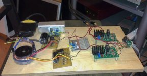
So after sorting out a few last (when is it ever last) things with my sapphire build, my attention turned back to the J-mo. I wanted to tidy up the power supplies on this one and start some experiments with the circuit.
So I had some regulators from teddy pardo from an old build. These are a gyrator reg, and have a fair voltage drop - you need ~5-7V headroom. As it happened, this suited me as I didn't have a 18VAC tx, but do have a few 24VAC tx to hand. I etched a couple of rectifier boards to give me basic rectification and filtering, and then to feed 2 teddyregs. The end idea here is to go full dual mono but for testing purposes I used just one Tx with one secondary supplying each reg.
The teddyregs have a bit of a bad rep for 2 reasons: one is the high headroom needed, and secondly, they are highish output impedance. I gather newer versions of these address this, but mine don't. Anyway, I am happy to report that the new PS gives a good improvement over a single supply (a salas shunt). The same melodic/warmish note is there, but there is really good slam to the amp now, and the detail is improved I think. I'm still listening as I type, but itsa good step forward for this amp.
Next up is to have a go at those LEDs on the cathodes of the fet and mosfet...... I wanted to have a listen at a number of points along the way so that I could get a handle on what each thing was doing.
Fran
Attachments
Well, I got derailed a little. I didn't get to try the LEDs yet. However I did go back and look at the Tx. The one pictured above is 25VA. I also tried a 200Va one (both of these cases had one secondary to each channel. I could hear no difference with the Tx size - next up is to try one for each channel.
Fran
Fran
More than other circuits, with the single-ended topology you really do hear the power supply. The PSRR is relatively low, so whatever is on the B+ is going in your ear more or less.
So thinking again about this LED bias. There are a few problems that need solving:
1. The bias through the jfet is only about 5mA - reading around, most LEDs seem to work best in the 10-20mA range, so that may be an issue. Apparently some do work out ok at lower current (aim for the dimmest oldest ones I can find) but you need to so the curves to find out.
2. The mosfet bias at 180mA is fairly high, and would take an array of LEDs to cope with that current. Might be better to think in terms of a "normal" ccs - perhaps a 317 ccs to start with.
My tx are due for delivery tomorrow so hoping to try out full dual mono over the weekend.
Fran
I haven't looked at it in detail, but perhaps the best route is to use a JFET CCS on the JFET stage, and a MOSFET CCS on the MOSFET stage. Whether you have enough voltage drop to implement these, or any alternatives like the LM317-based CCS is something you'll have to check for yourself. I have a feeling it may be a bit tight.
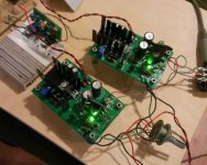
I received the new transformers today so tonight I went back to try dual mono. To my ears there is an expansion in the sound, more immediacy. Its not huge but certainly noticeable. I'm not terribly surprised - after all its what I've heard in other amps. However, I didn't think there would me any difference due to the low current draw of the J-Mo and the size of the Tx I was using - ~250VA (new ones are 30VA).
So 1-up for dual mono.
I also made up a pair of LM317 based CCS to try out. I haven't listened to these yet, but a 6.8R resistor works out to 184mA. I'll hopefully sub them in and try it out tomorrow.
Fran
So 1-up for dual mono.
I also made up a pair of LM317 based CCS to try out. I haven't listened to these yet, but a 6.8R resistor works out to 184mA. I'll hopefully sub them in and try it out tomorrow.
Fran
Attachments
Looks interesting. Very compact too, only vertical space required for the sub!
Re-reading back though a few posts, I remembered a couple of things about the circuit design:
1. The 2nd harmonic is balanced in that the input JFET produces a bit less than the output MOSFET for all but the lightest of loads ... but if you put a CSS on the MOSFET then the distortion will become limited by the input stage for all loads. So you really need to do both stages to get any real benefit to the output distortion.
2. The PSRR of the JMo2 is low, and given the high current draw it takes a bit of work to get the power ripple low enough to slip under the noise floor of the circuit itself. The companion power supply that goes with the JMo2 (scroll to the end of this page) does this by adding the 10R dropping resistor (forming a CRC filter stage) and the 2k2 resistor + 220 uF cap before the MOSFET gate. [ok, yeah, I suppose a simple LM317 would do that job just as well, but the output noise on those things...]
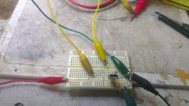
Tonight I got some time to rig up a test jig to look for LEDs with the correct characteristics for biasing the jfet. I made up a 5mA CCS using a LM317 and 240R resistor and double checked the current using a 1R resistor. I ended up testing about 50 different LEDs I had to hand (mostly the grab bag kind of stuff you can pick up for small money here and there).
So I got 2 green 3mm LEDs that gave me a Vf of 2.1V at 5.6mA which I think might be the best fit for the circuit.
Interesting aside: I got a huge variance in the LEDs tested, and not always related to colour at that current. I had some yellow that had a drop of 3.8V at 5mA, and other yellow with a drop of 1.9V. Lowest I got was some red at 1.6V.
RE: the PSU - right now I'm using a simple raw rectification folowed by a "teddy pardo regulator" - a gyrator reg. Output is supposedly quiet but a little high impedance (haven't scoped it). I'm waiting on some parts to build a series pass reg with an LED reference which should be pretty quiet as well. If its OK with you Richard, I might also home-etch a pair of your PSU boards to try? If I did that would there be an advantage to using something quieter as a reference than the zeners (zener noise floor already below the rest?).
Did I mention that I really like this amp? I know the sapphire seems to be regarded as the higher end one (which I will be going back to tweak when I'm through with this one), and design maybe with more "finesse", but this amp has a gorgeous sound with the k701. Zero listening fatigue, never sharp or tizzy, and yet sparkly enough on the highs to shine!!
Fran
Attachments
Consider the PS boards in the mail. Think of it as remuneration for your bench work.
The Sapphire and J-Mo2 are about as different as might be imagined, considering they are both from me. It's not right/wrong or better/worse but rather the embodiment of two alternative routes towards the same goal: enjoyable headphone listening.
The Sapphire and J-Mo2 are about as different as might be imagined, considering they are both from me. It's not right/wrong or better/worse but rather the embodiment of two alternative routes towards the same goal: enjoyable headphone listening.
Last edited:
Purdy green lights....
Wow - thanks indeed Richard!!
See the pic - purdy green lights!!
Fitting went smoothly. I fitted them, and did have to adjust the voltage a little on the trimmer. I've been listening now for the last hour or so and my impression is that there is more attack on transients. There's a track I use for testing - from Ulrich Schnauss "Long Way to Fall". Anyway, the opening track has this synth start which is overlaid by piano about 20 secs in. With the LEDs the strike of the piano key is more noticeable - sharper transient response?
When I first heard that I was a bit worried, was the amp now going to sound a bit harsh or sibilant. But very soon that worry could be laid to rest.
Overall I think the tweaking I've done (so far!) has had a positive impact on the SQ. I don't think the change is massive, nor does it alter the basic tone of the amp, but I think it enhances it. Do I have measurements of any kind to back up what I'm saying..... Nope!!
Fran
Attachments
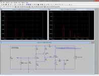
According to LTSPice, the CSS on the MOSFET source isn't going to do much for you. The distortion signature is generated by the input JFET stage.
Before you ask: no, a CSS on the JFET source is not going to work, since the gain is determined by that source resistor ... it becomes "infinity" with a CSS, so the gain falls to unity.
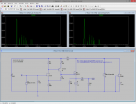
below, FFT "formal[1]" is with CSS, "formal" is with the 30 ohm resistor.
*edit* ah, hell ... that's with the 10x gain version, which has the really lousy performance JFET stage. Lemme run that again with the 3x gain version and re-post.
Before you ask: no, a CSS on the JFET source is not going to work, since the gain is determined by that source resistor ... it becomes "infinity" with a CSS, so the gain falls to unity.
below, FFT "formal[1]" is with CSS, "formal" is with the 30 ohm resistor.
*edit* ah, hell ... that's with the 10x gain version, which has the really lousy performance JFET stage. Lemme run that again with the 3x gain version and re-post.
Attachments
Last edited:
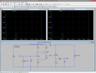
Let's try again. With a small enough time step interval this time so the FFT is accurate.
You can see that the CCS does have an influence here, dropping the output harmonics to the level of the JFET input stage (as shown on the plots as the "gate" trace, the voltage going into the MOSFET.) However, while the distortion is reduced the overall character - as indicated by the 2-3-4... harmonic progression is similar so I wouldn't expect the sound to be greatly affected. A little cleaner maybe, a little less rich.
"formal.fft" is with 30R, "formal[1].fft" is with the CCS.
Attachments
Last edited:
Sure, why not? The change is quite large actually, 3x less 2nd harmonic. Well, size is relative but I do think it would be audible, yes. Moreover there is no other good reason to suppose the sound would change as the result of the switch.
Grand. I suppose what I'm trying to get a handle on is the measured reason for my subjective impressions - if that can be found.
Fran
Fran
100%
I call it "proud papa syndrome"
extra effort made = expectation of better sound
Also, it can be impossible to avoid, even when you are aware of it.
At the end of the day, I've made my few changes - and I suppose what's needed now is for someone else to do the same thing (or their variation) and report back to see if they hear a change too. That kind of consensus (which is also open to influence) would help. I've had fun, learned some things, and have a (IMHO) great sounding HPA at the end of it. The few mods are basic enough and very cheap - I can't see that it would lead anyone too far astray!! and I still have to work on the power supplies!!
Fran
- Status
- Not open for further replies.
- Home
- Amplifiers
- Headphone Systems
- J-Mo Mk II headphone amplifier