I dont know but im thinking faster transistor means faster oscillation, is this means more prone to osc ? Or its more stable as you say ?Depends on what you call fast. 10Mhz isn't fast. For Driver transistors I look for ft of 100MHz+ hence my liking of bootstrapping. Along with using MOSFETs for the output transistors. Faster transistors mean better stability margins for a given ULGF.
Oh i forgot to add a resistor (two more diodes) in my bias circuit of the OPS.
it must be upside vbe transistor and the downer must be 47ohm instead 22
it must be upside vbe transistor and the downer must be 47ohm instead 22
I lowered very very the distort in this way but im not using 4 diode drops here too.
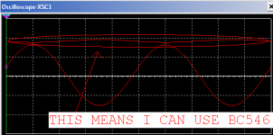
LOOK @ MY PERFECT OPS WITH 4 DROPS <-------------
IT DO/HIT 0.000% just without error correction
The only problem 700-800ma standby current 😀
This is pretty CLASS A 😀
30W standby dissip per tr.
If you want it 200mA R1, R10, R11 and R12 must be 2Megaohm per resistor
If you want it even less connect Q1 and Q2's collectors together and Q5 and Q6's collectors together 😀
Next step to add emitter resistors, short circuit protection and a PIC microcontroller displaying the POWER 😀
im paradoxed here but i think ill go lcd instead 7seg..
Attachments
Last edited:
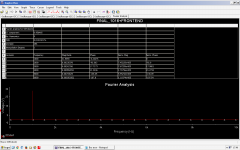
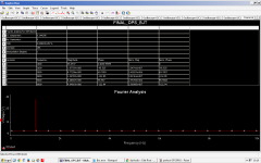
Ohh this is very interesting:
I need to make that last sch to examine which harmonics are better, even or odd. 😀 For my ear 😀
Distortion Analyser
I need to make that last sch to examine which harmonics are better, even or odd. 😀 For my ear 😀
Distortion Analyser
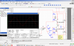
Why the perfect OPS didnt work with load, i just found out that ?
it works but with 2 diode bias, i tried with 3 (two resistors instead middle diode drop injecting signal there) and its the same as 4 😕
i want it with three or four 🙁
with two there is 0.08% thd without correction. with 4 there are 0.000 without load and 3rd harmonic is zero magnitute.
it works but with 2 diode bias, i tried with 3 (two resistors instead middle diode drop injecting signal there) and its the same as 4 😕
i want it with three or four 🙁
with two there is 0.08% thd without correction. with 4 there are 0.000 without load and 3rd harmonic is zero magnitute.
Last edited:
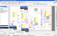
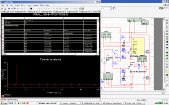
is this the best working variant, compromise ?:
Look how i inject the signal 😀
At the collector of the vbe, its freaky 😀
Look how i inject the signal 😀
At the collector of the vbe, its freaky 😀
Attachments
Last edited:
understand what ? or someday i will understand it ?someday he will understand 🙂
I have forgot that virtual bjts are with 0.7 voltage drop instead 1.3.
I will change that and try again. 😛
help me with this.
i tested the hfe of the two stages of a darlington.
i found out 142 for the 1st and 100 for the 2nd (virtual).
i read somewhere that darlington total beta = b1*b2 => 142*100 = 14200
which is not equal to 665 (total beta of the simulated circuit)
another paradox fuks me -> what is better -> to simulate my darlingtons as bd139+virtual as in attachment or to use one virtual with high beta and a series diode to its base to simulate another drop. (i change the drop in the model but theres no difference like when i change beta)
Attachments
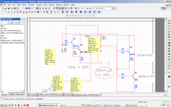
I found out this is from the 70ohm resistor.
woow this resistor makes the beta very unstable, why they use it in darlingtons 😡@
Im very very puzzled now
woow this resistor makes the beta very unstable, why they use it in darlingtons 😡@
Im very very puzzled now
Last edited:
Sooo easy not to see any harmonics on a linear scale. Too bad the ear doesn't work that way. Still using all available energy to resist learning?
Depends on what you call fast. 10Mhz isn't fast. For Driver transistors I look for ft of 100MHz+ hence my liking of bootstrapping. Along with using MOSFETs for the output transistors. Faster transistors mean better stability margins for a given ULGF.
2sd947. They are 150Mhz but only 5 Watts. However 5W output transistors are enough for 90W amplifier.
Sooo easy not to see any harmonics on a linear scale. Too bad the ear doesn't work that way. Still using all available energy to resist learning?
The kid is very ecstatic in his find, i figure given him a book he will skip on all the text and work on the figures..........
........me during my school days I skip on all the figures and work on the text 😀
just don't hurt yourself kid...........😉
......and the neighbourhood too 😀
BTW look for those used in CRT vertical deflection transistor they are ideally fast. Google will help you out 🙂
The kid is very ecstatic in his find, i figure given him a book he will skip on all the text and work on the figures..........
........me during my school days I skip on all the figures and work on the text 😀
just don't hurt yourself kid...........😉
......and the neighbourhood too 😀
Ofcourse, it seems that you are no kids.
my neighbourhood like music and pushing it to the limit 😀
im the first one who is liken by the neighbourhood for the music 😀
firstly they didnt wanted, but this was a very short period.
now they cant wait for music 😀
i have big speaker, listen for hours and police never comes.
the best is this speaker at the balcony, resonating windows 😀
its AWSOME
BTW look for those used in CRT vertical deflection transistor they are ideally fast. Google will help you out 🙂
Thanks, my father have a small service and a lot of pcb's (monitors, tv's, etc.)
i will search for fasters.
P.S. Im going to open a book because i was thinking i have learnt and understanded LTP very well, but i cant get it.
Im pretty sure injecting signal into the middle is more better than from up or down.
.. aand Double bootstrapping is the sh*t
Last edited:
Why is thread still alive when the OP is undertaking risky behaviour with mains?
??? mains ??
only low voltage here

- Status
- Not open for further replies.
- Home
- Amplifiers
- Solid State
- Is this good ?