Hello David
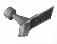
What is that a recording horn you play into??
Rob🙂
Yes, but there is something a little unusual about it.
David
In that recording horn, there seems to be a
"parabolic like" section inbetween two
"exponential like" ones ...
Is this what you mean ?
"parabolic like" section inbetween two
"exponential like" ones ...
Is this what you mean ?
Last edited:
There seems to be a "parabolic like" section
inbetween two "exponential like" ones ...
Is this what you mean ?
Exactly. It looks to me to be two exponential sections of different flare rates. (With maybe a soft transition.) I believe it was Olson that had a textbook example of two linked exponential sections and how it impacted their acoustic impedance. All the early texts concentrate on a horn as being an acoustic transformer that links an acoustic impedance at the mouth to an acoustic impedance at the throat. Two linked exponential horns would do that in two steps.
Can't remember what the advantage was supposed to be!
David S.
I was thinking something like "acoustical impedance transforming device with aspects of directivity control".
Rolls off the tongue.
Extra credit question: what's unique about the horn in the attached picture?
David S.
haha rolls off like butter from a hot knife....
i have no idea about the recording horn though

It gets better!
1) Here is where Geddes "OS Waveguide" comes from, and there it is called a HORN, circa 1940.
Title: The Acoustical Impedance of an Infinite Hyperbolic Horn
Author: J. E. Freehafer
Publication: ASA-J, Vol. 11, No. 4, p. 467-476 (Apr-1940)
URL: Cookies Required
Abstract: In discussing the acoustical properties of horns, it is in general a mathematical neceessity to assume plane waves. In the case of a horn in the form of an hyperboloid of one sheet, however, it is possible to avoid this assumption and to obtain an exact solution to the problem. The analysis, carried through with the aid of the differential analyzer, leads to curves representing the acoustical resistance and reactance as functions of the ratio of the radius of the throat to the wave length. Comparison with the conical horn shows that the hyperbolic is superior.
2) Horn shape optimization studies, which address the tradeoff between efficiency (the ratio of acoustic energy that exits/enters the horn) and dispersion uniformity (the degree to which, frequency response is of constant magnitude accross a specified coverage angle in the far field), have been recently conducted by faculty and students of Uppsala University, Sweden. These studies, described in the referenced articles, are yielding horn shapes that are not like those addresses by Freehafer and a lot later by Geddies. . A typical horn profile and related dispersion patterns are shown in the attached diagrams. The reference horn is conical. The Freehafer horn is asymptotically conical as well.
Regards,
WHG
References: Horn Shape Optimization
Title (1): Shape Optimization for Acoustic Wave Propagation Problems
Title (2): Doctoral Thesis, Comprehensive Summary
Author: Udawalpola, Rajitha
Affiliation: Uppsala University, Disciplinary Domain of Science and Technology, Mathematics and Computer Science
Publication: Acta Universitatis Upsaliensis, 14-Jan-2010
Abstract(1): Boundary shape optimization is a technique to search for an optimal shape by modifying the boundary of a device with a pre-specified topology. We consider boundary shape optimization of acoustic horns in loudspeakers and brass wind instruments. A horn is an interfacial device, situated between a source, such as a waveguide or a transducer, and surrounding space.
Abstract(2): Horns are used to control both the transmission properties from the source and the spatial power distribution in the far-field (directivity patterns).
Abstract(3): Transmission and directivity properties of a horn are sensitive to the shape of the horn ?are. By changing the horn ?are we design transmission efficient horns. However, it is difficult to achieve both controllability of directivity patterns and high transmission efficiency by using only changes in the horn ?are. Therefore we use simultaneous shape and so-called topology optimization to design a horn/acoustic-lens combination to achieve high transmission efficiency and even directivity.
Abstract(4): We also design transmission efficient interfacial devices without imposing an upper constraint on the mouth diameter. The results demonstrate that there appears to be a natural limit on the optimal mouth diameter.
Abstract(5): We optimize brass wind instruments with respect to its intonation properties. The instrument is modeled using a hybrid method between a one-dimensional transmission line analogy for the slowly flaring part of the instrument, and a finite element model for the rapidly faring part.
Abstract(6): An experimental study is carried out to verify the transmission properties of optimized horn. We produce a prototype of an optimized horn and then measure the input impedance of the horn. The measured values agree reasonably well with the predicted optimal values.
Abstract(7): The finite element method and the boundary element method are used as discretization methods in the thesis. Gradient-based optimization methods are used for optimization, in which the gradients are supplied by the adjoint methods.
Title: Shape Optimization of an Acoustic Horn
Author (1): Erik BÄangtsson
Author (2): Daniel Norelan
Author (3): Martin Berggre
Affiliation: Uppsala University, Department of Information Technology
Publication: Uppsala University, Tech. Report 2002-019, 8-May-2002
URL: http://www.it.uu.se/research/publications/reports/2002-019/2002-019-nc.pdf
Abstract(1): Shape optimization of an acoustic horn is performed with the goal to minimize the portion of the wave that is reflected. The analysis of the acoustical properties of the horn is performed using a finite element method for the Helmholtz equation.
Abstract(2): The optimization is performed employing a BFGS Quasi-Newton algorithm, where the gradients are provided by solving the associated adjoint equations. To avoid local solutions to the optimization problem corresponding to irregular shapes of the horn, a filtering technique is used that applies smoothing to the design updates and the gradient. This smoothing technique can be combined with Tikhonov regularization.
Abstract(3): However, the use of smoothing is crucial to obtain sensible solutions. The smoothing technique we use is equivalent to choosing a representation of the gradient of the objective function in an inner product involving second derivatives along the design boundary. Optimization is performed for a number of single frequencies as well as for a band of frequencies. For single frequency optimization, the method shows particularly fast convergence with indications of super-linear convergence close to optimum.
Abstract(4): For optimization on a range of frequencies, a design was achieved providing a low and even reflection throughout the entire frequency band of interest.
Title: Topology Optimization of an Acoustic Hrorn
Author(1): Eddie Wadbro (1)
Author(2): Martin Berggren (1),(2)
Affiliation(1): Uppsala University
Affiliation(2): Swedish Defence Research Agency
Publication: Uppsala University, Tech. Report 2006-009, 8-May-2002
Abstract(1): We present a method for topology optimization of an acoustic horn with the aim of radiating sound as efficiently as possible. Using a strategy commonly employed for topology optimization of elastic structures, we optimize over a scalar function indicating presence of material. The Helmholtz equation modeling the wave propagation is solved using the finite element method and the associated adjoint equation provides the required gradients.
Abstract(2): Numerical experiments validates that the result of the optimization provides horns with the desired acoustical properties. The resulting horns are very efficient in the frequency span subject to optimization.
Title: Topology Optimization for Acoustic Wave Propagation Problems
Author: Eddie Wadbro
Affiliation: Uppsala University, Department of Information Technology
Publication: Uppsala University, Dissertation 2006-009, 1-Oct-2006
URL: http://www.it.uu.se/research/publications/lic/2006-009/2006-009.pdf
The aim of this study is to develop numerical techniques for the analysis and optimization of acoustic horns for time harmonic wave propagation. An acoustic horn may be viewed as an impedance transformer, designed to give an impedance matching between the feeding waveguide and the surrounding air. When modifying the shape of the horn, the quality of this impedance matching changes, as well as the angular distribution of the radiated wave in the far field (the directivity).
Abstract(2): The dimensions of the horns considered are in the order of the wavelength. In this wavelength region the wave physics is complicated, and it is hard to apply elementary physical reasoning to enhance the performance of the horn. Here, topology optimization is applied to improve the efficiency and to gain control over the directivity of the acoustic horn.
Title: Shape and Topology Optimization of an Acoustic Horn-Lens Combination
Author (1): Eddie Wadbro
Author (2): Rajitha Udawalpola,
Author (3): Martin Berggren
Affiliation(1): Uppsala University
Publication: Journal of Computational and Applied Mathematics (ISSN 0377-0427), Vol. 234, No.6, pg. 1781,Jul-2010
Abstract: Using gradient-based optimization combined with numerical solutions of the Helmholtz equation, we design an acoustic device with high transmission efficiency and even directivity throughout a two-octave-wide frequency range. The device consists of a horn, whose flare is subject to boundary shape optimization, together with an area in front of the horn, where solid material arbitrarily can be distributed using topology optimization techniques, effectively creating an acoustic lens.
If you say so - lets go ahead...
😀
As much as one could have agreed to that definition *before* Earl Geddes has messed up this term (waveguide) by popularizing it for his OS boundary shaped horns (out of commercial interests), the much one must disagree *nowadays*
Michael
1) Here is where Geddes "OS Waveguide" comes from, and there it is called a HORN, circa 1940.
Title: The Acoustical Impedance of an Infinite Hyperbolic Horn
Author: J. E. Freehafer
Publication: ASA-J, Vol. 11, No. 4, p. 467-476 (Apr-1940)
URL: Cookies Required
Abstract: In discussing the acoustical properties of horns, it is in general a mathematical neceessity to assume plane waves. In the case of a horn in the form of an hyperboloid of one sheet, however, it is possible to avoid this assumption and to obtain an exact solution to the problem. The analysis, carried through with the aid of the differential analyzer, leads to curves representing the acoustical resistance and reactance as functions of the ratio of the radius of the throat to the wave length. Comparison with the conical horn shows that the hyperbolic is superior.
2) Horn shape optimization studies, which address the tradeoff between efficiency (the ratio of acoustic energy that exits/enters the horn) and dispersion uniformity (the degree to which, frequency response is of constant magnitude accross a specified coverage angle in the far field), have been recently conducted by faculty and students of Uppsala University, Sweden. These studies, described in the referenced articles, are yielding horn shapes that are not like those addresses by Freehafer and a lot later by Geddies. . A typical horn profile and related dispersion patterns are shown in the attached diagrams. The reference horn is conical. The Freehafer horn is asymptotically conical as well.
Regards,
WHG
References: Horn Shape Optimization
Title (1): Shape Optimization for Acoustic Wave Propagation Problems
Title (2): Doctoral Thesis, Comprehensive Summary
Author: Udawalpola, Rajitha
Affiliation: Uppsala University, Disciplinary Domain of Science and Technology, Mathematics and Computer Science
Publication: Acta Universitatis Upsaliensis, 14-Jan-2010
Abstract(1): Boundary shape optimization is a technique to search for an optimal shape by modifying the boundary of a device with a pre-specified topology. We consider boundary shape optimization of acoustic horns in loudspeakers and brass wind instruments. A horn is an interfacial device, situated between a source, such as a waveguide or a transducer, and surrounding space.
Abstract(2): Horns are used to control both the transmission properties from the source and the spatial power distribution in the far-field (directivity patterns).
Abstract(3): Transmission and directivity properties of a horn are sensitive to the shape of the horn ?are. By changing the horn ?are we design transmission efficient horns. However, it is difficult to achieve both controllability of directivity patterns and high transmission efficiency by using only changes in the horn ?are. Therefore we use simultaneous shape and so-called topology optimization to design a horn/acoustic-lens combination to achieve high transmission efficiency and even directivity.
Abstract(4): We also design transmission efficient interfacial devices without imposing an upper constraint on the mouth diameter. The results demonstrate that there appears to be a natural limit on the optimal mouth diameter.
Abstract(5): We optimize brass wind instruments with respect to its intonation properties. The instrument is modeled using a hybrid method between a one-dimensional transmission line analogy for the slowly flaring part of the instrument, and a finite element model for the rapidly faring part.
Abstract(6): An experimental study is carried out to verify the transmission properties of optimized horn. We produce a prototype of an optimized horn and then measure the input impedance of the horn. The measured values agree reasonably well with the predicted optimal values.
Abstract(7): The finite element method and the boundary element method are used as discretization methods in the thesis. Gradient-based optimization methods are used for optimization, in which the gradients are supplied by the adjoint methods.
Title: Shape Optimization of an Acoustic Horn
Author (1): Erik BÄangtsson
Author (2): Daniel Norelan
Author (3): Martin Berggre
Affiliation: Uppsala University, Department of Information Technology
Publication: Uppsala University, Tech. Report 2002-019, 8-May-2002
URL: http://www.it.uu.se/research/publications/reports/2002-019/2002-019-nc.pdf
Abstract(1): Shape optimization of an acoustic horn is performed with the goal to minimize the portion of the wave that is reflected. The analysis of the acoustical properties of the horn is performed using a finite element method for the Helmholtz equation.
Abstract(2): The optimization is performed employing a BFGS Quasi-Newton algorithm, where the gradients are provided by solving the associated adjoint equations. To avoid local solutions to the optimization problem corresponding to irregular shapes of the horn, a filtering technique is used that applies smoothing to the design updates and the gradient. This smoothing technique can be combined with Tikhonov regularization.
Abstract(3): However, the use of smoothing is crucial to obtain sensible solutions. The smoothing technique we use is equivalent to choosing a representation of the gradient of the objective function in an inner product involving second derivatives along the design boundary. Optimization is performed for a number of single frequencies as well as for a band of frequencies. For single frequency optimization, the method shows particularly fast convergence with indications of super-linear convergence close to optimum.
Abstract(4): For optimization on a range of frequencies, a design was achieved providing a low and even reflection throughout the entire frequency band of interest.
Title: Topology Optimization of an Acoustic Hrorn
Author(1): Eddie Wadbro (1)
Author(2): Martin Berggren (1),(2)
Affiliation(1): Uppsala University
Affiliation(2): Swedish Defence Research Agency
Publication: Uppsala University, Tech. Report 2006-009, 8-May-2002
Abstract(1): We present a method for topology optimization of an acoustic horn with the aim of radiating sound as efficiently as possible. Using a strategy commonly employed for topology optimization of elastic structures, we optimize over a scalar function indicating presence of material. The Helmholtz equation modeling the wave propagation is solved using the finite element method and the associated adjoint equation provides the required gradients.
Abstract(2): Numerical experiments validates that the result of the optimization provides horns with the desired acoustical properties. The resulting horns are very efficient in the frequency span subject to optimization.
Title: Topology Optimization for Acoustic Wave Propagation Problems
Author: Eddie Wadbro
Affiliation: Uppsala University, Department of Information Technology
Publication: Uppsala University, Dissertation 2006-009, 1-Oct-2006
URL: http://www.it.uu.se/research/publications/lic/2006-009/2006-009.pdf
The aim of this study is to develop numerical techniques for the analysis and optimization of acoustic horns for time harmonic wave propagation. An acoustic horn may be viewed as an impedance transformer, designed to give an impedance matching between the feeding waveguide and the surrounding air. When modifying the shape of the horn, the quality of this impedance matching changes, as well as the angular distribution of the radiated wave in the far field (the directivity).
Abstract(2): The dimensions of the horns considered are in the order of the wavelength. In this wavelength region the wave physics is complicated, and it is hard to apply elementary physical reasoning to enhance the performance of the horn. Here, topology optimization is applied to improve the efficiency and to gain control over the directivity of the acoustic horn.
Title: Shape and Topology Optimization of an Acoustic Horn-Lens Combination
Author (1): Eddie Wadbro
Author (2): Rajitha Udawalpola,
Author (3): Martin Berggren
Affiliation(1): Uppsala University
Publication: Journal of Computational and Applied Mathematics (ISSN 0377-0427), Vol. 234, No.6, pg. 1781,Jul-2010
Abstract: Using gradient-based optimization combined with numerical solutions of the Helmholtz equation, we design an acoustic device with high transmission efficiency and even directivity throughout a two-octave-wide frequency range. The device consists of a horn, whose flare is subject to boundary shape optimization, together with an area in front of the horn, where solid material arbitrarily can be distributed using topology optimization techniques, effectively creating an acoustic lens.
Attachments

Those polars look really nice, but its only two octaves shown.
Have any additional information ? - didn't find it in the links you posted
Michael
Have any additional information ? - didn't find it in the links you posted
Michael
More Later
Hi M.
The references given represent the extent of the information I have at the moment. As horns by nature are band-pass devices, I do not expect shape optimization methods to be successful over much more than one decade of frequency bandwidth. For me, this study is a work in progress. In time I will post definitive findings here. What has become clear, so far, is that under the 1-P wave assumption, an optimum horn design cannot be achieved. Hopefully a simple design regime will emerge from further study.
Regards,
Bill
Those polars look really nice, but its only two octaves shown.
Have any additional information ? - didn't find it in the links you posted
Michael
Hi M.
The references given represent the extent of the information I have at the moment. As horns by nature are band-pass devices, I do not expect shape optimization methods to be successful over much more than one decade of frequency bandwidth. For me, this study is a work in progress. In time I will post definitive findings here. What has become clear, so far, is that under the 1-P wave assumption, an optimum horn design cannot be achieved. Hopefully a simple design regime will emerge from further study.
Regards,
Bill
Last edited:
I wonder how well a "hornguide" would sell?
Hi bentoronto,
Probably about as well as a "wavehorn".
Come to think of it, after more than 60 years perhaps it's time for the venerable "Klipschorn" to be re-badged and given a new lease of life as the "Klipschwaveguide" - a name that also rolls off the tongue 🙂.
Kind regards,
David
More Now!
Hi M,
Just Found It:
Regards
Bill
Title: EGO Shape Optimization of Horn Loaded Loudspeakers
Author(1): Rick C. Morgans (1)
Author (2): Anthony C. Zander (1)
Author (3): Colin H. Hansen (1)
Author(3): David J. Murphy (2)
Affiliation(1): School of Mechanical Engineering, The University of Adelaide, SA, 5005
Affiliation(2): Krix Loudspeakers, Hackham SA, 5163
Publication: RCM_SMSMEO_paper.tex; 1/03/2007; 16:48, Kluwer Academic Publishers, 2007
URL: http://www.mecheng.adelaide.edu.au/...s/2008/preprint_morgans_optimization_2008.pdf
Abstract(1): Horn loaded loudspeakers increase the efficiency and control the spatial distribution of sound radiated from the horn mouth. They are often used as components in cinema sound systems where it is desired that the sound be broadcast onto the audience uniformly at all frequencies, improving the listening experience.
Abstract(2): The sound distribution, or beamwidth, is related to the shape of the horn and can be predicted by numerical methods, such as the boundary element or source superposition method, however the cost of evaluating the objective function is high. To
Abstract(3): To overcome this a surrogate optimization method called Efficient Global Optimization (EGO) was used with a spline based parameterization to find the shape of the horn that gives a frequency independent beamwidth, thus giving a high quality listening experience. (Submitted for the SMSMEO-06 special issue).
Those polars look really nice, but its only two octaves shown.
Have any additional information ? - didn't find it in the links you posted
Michael
Hi M,
Just Found It:
Regards
Bill
Title: EGO Shape Optimization of Horn Loaded Loudspeakers
Author(1): Rick C. Morgans (1)
Author (2): Anthony C. Zander (1)
Author (3): Colin H. Hansen (1)
Author(3): David J. Murphy (2)
Affiliation(1): School of Mechanical Engineering, The University of Adelaide, SA, 5005
Affiliation(2): Krix Loudspeakers, Hackham SA, 5163
Publication: RCM_SMSMEO_paper.tex; 1/03/2007; 16:48, Kluwer Academic Publishers, 2007
URL: http://www.mecheng.adelaide.edu.au/...s/2008/preprint_morgans_optimization_2008.pdf
Abstract(1): Horn loaded loudspeakers increase the efficiency and control the spatial distribution of sound radiated from the horn mouth. They are often used as components in cinema sound systems where it is desired that the sound be broadcast onto the audience uniformly at all frequencies, improving the listening experience.
Abstract(2): The sound distribution, or beamwidth, is related to the shape of the horn and can be predicted by numerical methods, such as the boundary element or source superposition method, however the cost of evaluating the objective function is high. To
Abstract(3): To overcome this a surrogate optimization method called Efficient Global Optimization (EGO) was used with a spline based parameterization to find the shape of the horn that gives a frequency independent beamwidth, thus giving a high quality listening experience. (Submitted for the SMSMEO-06 special issue).
Never!
Hello David,
That would be an posthumous insult to "Dope from Hope".
While not known for it, his MF & HF horn designs were equally elegant as well.
Bill
Hi bentoronto,
Probably about as well as a "wavehorn".
Come to think of it, after more than 60 years perhaps it's time for the venerable "Klipschorn" to be re-badged and given a new lease of life as the "Klipschwaveguide" - a name that also rolls off the tongue 🙂.
Kind regards,
David
Hello David,
That would be an posthumous insult to "Dope from Hope".
While not known for it, his MF & HF horn designs were equally elegant as well.
Bill
In all this discussion no one has really gotten it right thus far.
The term "Acoustic Waveguide" was first used (to my knowledge) in my 1991 paper on the subject. In this paper I discussed a new approach to analyzing duct contours. Prior to this paper all discussions of "horns" used Webster's approach which can very easily be shown to be wrong. SInce my approach was exact and completely different, hence I did not want to use the term "horn" for this new class of devices, so I used "Acoustic Waveguide". To me that's were the term comes from, but others may disagree (and I sure they will, they always do.)
In this paper I show how to use seperable coordinates to analyze not only the imepdance of the device, but more importantly the wavefront shape, which is required to calculate the directivity. The horn equation cannot do this. I found the most interesting shape to be the OS, although numerous shapes were discussed. I found, as noted above, that Freehafer had published a treatis on the OS "horn" although in that paper there was no discussion of waveshape or directivity, only impedance. I had not seen this paper when I started mine.
I did not use the term "Waveguides" for commercial purposes as stated, this is obvious by its use in 1991, long before I ever made anything commercially.
As stated, "waveguide" sounds cool, so before long everyone renamed their devices "waveguides". There was and is no standrad deffinition so this was possible. I stick by my original usage in 1991 and have never deviated from that. Under this usage, there is a significant difference between a waveguide and a horn. True, all "waveguides" are horns, i.e. all waveguide shapes can be analyzed with the "horn equation" (and the results are always incorrect since the equation is incorrect) but not all horns are waveguides - only a very few shapes fit this latter restriction (see my original paper and Putland), most notably the OS, however there are Prolate and Ellipsoidal shapes as well as the straight walled conical horn, which is also an exact waveguide.
Last edited:
thanks for correcting the more ignorant/sceptical there Gedlee.
what do you make of the waveguide/horn i posted? its elliptical widthways, dispersion angle is 70°x50°, and the profile is stated being exponential. another poster commented that it WOULD NOT be CD, and HF would narrow as f increases. this is fine as it follows what all speakers do in general, except maybe CD horns. im no expert in either field.
i would be interested in any opinions you may have in the horn(?) i posted Earl.
thanks for taking an interest, and for any advice/opinion you can offer
Greg
Hi Earl,
I’m not sure you are any different than the rest of us with regard to debating what is basically a semantic issue. Your definition of waveguide, if I understand it right, is that it can only be applied to the particular few horn designs that are 1P devices free from higher order modes. Even if you were the first to apply the term to this subclass of horns, that doesn’t constrain it to those alone.
Obviously the term came from RF waveguides that preceded it. As you know they are ducts for RF energy, generally closed systems with beginning and ending points. (If they are opened at one end, the RF engineer would call them an RF Horn.) In that regard we are all misusing the term.
If you want to refer to your design as a “waveguide free from higher order modes”, I’d buy that. To say that a flared device can only be termed a waveguide if it has those particular qualities can’t be justified since, even a device of poor performance will inevitably guide waves from throat to mouth. If that becomes the common thinking of what the term means, it’s hard to argue that the general population has it wrong.
In the end you have conscripted a term from its original usage and are now trying to give it a more restrictive definition in a parallel field. I don’t think it works that way.
David S.
Hi Earl,
Your definition of waveguide, if I understand it right, is that it can only be applied to the particular few horn designs that are 1P devices free from higher order modes.
David S.
David
Use the term however you want.
The above is not my deffinition. First the OS is not 1P, the whole concept of 1P is obsolete as no device can be truely 1P. And even the OS is not free from HOM, it just has the lowest possible HOMs.
Very nice example David,
but as this thread seems to be a bit hairsplitting 😀 :
If the "recording horn" above is a horn ... direction
of cross sectional tapering should not be a criterion
in itself.
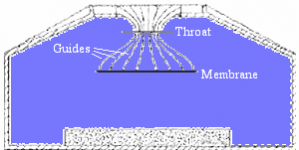
What is your criterion for not being a horn in case of
the Beveridge "diffraction modification device" ?
AFAIK Harold Beveridge refered to his device as
"acoustic lens" ?
but as this thread seems to be a bit hairsplitting 😀 :
If the "recording horn" above is a horn ... direction
of cross sectional tapering should not be a criterion
in itself.
What is your criterion for not being a horn in case of
the Beveridge "diffraction modification device" ?
AFAIK Harold Beveridge refered to his device as
"acoustic lens" ?
HoHoHo ….
Whom - but the most naive - you think you can make belive in you being Santa Claus, Earl?
LOL
😉
I mean – you know, I too love to give the child a fancy name – but its not driven by any commercial interest like seen from your bunch of patents.
Michael
Whom - but the most naive - you think you can make belive in you being Santa Claus, Earl?
LOL
😉
I mean – you know, I too love to give the child a fancy name – but its not driven by any commercial interest like seen from your bunch of patents.
Michael
As much as one could have agreed to that definition *before* Earl Geddes has messed up this term (waveguide) by popularizing it for his OS boundary shaped horns (out of commercial interests), the much one must disagree *nowadays*
Michael
In all this discussion no one has really gotten it right thus far.
I did not use the term "Waveguides" for commercial purposes as stated, this is obvious by its use in 1991, long before I ever made anything commercially.
thanks for correcting the more ignorant/sceptical there Gedlee.
Greg
What is your criterion for not being a horn in case of
the Beveridge "diffraction modification device" ?
Just that the area at the panel and the area at the exit are the same (or nearly so). Beveridge's intention was not to change the load on the panel, but to alter the wavefront shape.
The classic horn is an acoustic transformer: High pressure and low velocity at one end and low pressure and high velocity at the other end. Same as an electrical transformer or car transmission, power is constant but impedance is different. A recording horn is still a horn even if it runs in the opposite direction to what we are used to.
The other acoustic lenses are the ones that Bart Locanthi developed for wider dispersion at the end of a conventional horn. A waveguide with varying path length across its width.
David S.
Attachments
As much as one could have agreed to that definition *before* Earl Geddes has messed up this term (waveguide) by popularizing it for his OS boundary shaped horns (out of commercial interests), the much one must disagree *nowadays*
Michael
I don't think it is right to "blame" Earl for the use (or misuse) of the waveguide term. With all the CD horn development in the 80s and later, it was already becoming a popular euphemism for horns designed with a priority placed on polars or d.i.
David S.
Just that the area at the panel and the area at the exit are the same (or nearly so). Beveridge's intention was not to change the load on the panel, but to alter the wavefront shape.
...
http://www.bevaudio.com/technical/Bev_ES_reflection1.png
hmm ... quite a high ratio of area between entrance and
outlet like i see it.
Still i do not disagree concerning the intention or main
purpose of just changing the shape of the wavefront.
So i am fine with "acoustic lense", but it is a really special
- and ingenius - one.
When looking at this example, the "main intention" for
making a "diffraction modifying device" or "diffraction
control device" may also play a role for the wording to
use, and there seems to be some degree freedom for
every designer to choose his prefered term due to
his/her main intention ... taking also the master
plan for the whole 'speaker system' into acount.
In one case gain in LF radiation resistance may be
desired but in a different case it is not needed and
the "wavefront shaping" effect is the main intention.
Nevertheless in both cases the resulting device itself
may have similar functionality and shape also, but the
way it integrates to the whole concept is different.
This is why i would not bother naming Earl's devices
"Waveguide" while a similar device from same
"shape family" may be called "Horn" in a different
context.
My suggestion for compromise to move this away
from hairsplitting ...
Another device:
"Manger Holoprofile":
http://tecsart.com/media/products/medium/1268410938Manger_Holoprofile.jpg
Creating special names for diffraction modifiers seem
a good way out also ...
Last edited:
- Status
- Not open for further replies.
- Home
- Loudspeakers
- Multi-Way
- is this a horn or a waveguide?