Something to consider (but probably not practical) is to provide a software driver that uses the tube tester (and tube) in Spice, to simulate with the real tube. This would require a pretty fast PC interface to keep Spice humming along. The driver software could speed things up some by doing interpolations (using derivatives from previous test points, ie curve fittings of plate current, to estimate) between actual tube tests.
------------------------
Instead of arrays of relays for pin selection, you could just use a DIP header with the pin wiring done from one side to the other side of the header pins (soldered wires). Then just plug the header in to a ZIF socket on the tester to set up the tester. One DIP header for each distinct tube pin setup. A safety plastic box could flip over that for safety during testing. The heater wires might need a few pins in parallel for high current tubes. 500V to 1000V plate operation will need some double or triple spaced pins. I'm not aware of any ZIF banana plugs, but those on a plug board could do a nice job too.
Last edited:
My problem with the current kits is that they pulse the tube under test. In other words the tube is not operated at any level of plate load. Often the characteristics change when plate is heated up.
An "old fashioned" tube tester does not need to be complicated, basically it needs a variable grid voltage, a variable filament voltage, and variable screen and plate voltages. A computer can be used to add some AC test signal to the drive and a simple AC voltmeter across a current resistor in line with the plate can then measure the amplification. All the power can easily be provideed with adjustable switch mode power supplis. A number of cheap digital meters can be used to measure performance. I acquired all the parts from ePray for around USD $100.- (having plenty of tube sockets and misc parts). $500 USD for a ready build simple version would be a good deal for those who have the need for one.
An "old fashioned" tube tester does not need to be complicated, basically it needs a variable grid voltage, a variable filament voltage, and variable screen and plate voltages. A computer can be used to add some AC test signal to the drive and a simple AC voltmeter across a current resistor in line with the plate can then measure the amplification. All the power can easily be provideed with adjustable switch mode power supplis. A number of cheap digital meters can be used to measure performance. I acquired all the parts from ePray for around USD $100.- (having plenty of tube sockets and misc parts). $500 USD for a ready build simple version would be a good deal for those who have the need for one.
I think, for the world it would be best, when a common data format for the measured tube curves would exist. Then external tools can post-process the measured tube data, for example generating LT Spice models. Such a tool could then generate models from data of any curve tracer. CSV (comma seperated values) data can be read from any programming language, it would just need some specs what columns are required, what floating point format, and so on. And maybe a tool to convert the exported data from uTracer, eTracer, RoeTester to the "Universal Tube Tracer Data Format" UTTDF.A nice feature of etracer is making LT Spice models for a single tube or 2 to n tubes in parallel. For one tube you just save the data file then import it into Derek's program that spits out a Spice model of that exact tube. To create a spice model for let's say three EL 84's hooked in parallel triode strapped. You'd breadboard the 3 tubes together with 100 screen to plate resistors, and heat them from a separate AC supply. Then just bring the grid, cathode and plate leads to the etracer and trace your triple parallel tube as though it were one tube, it doesn't know it three tubes. The etracer not doing the heating. Save the data file then convert it to LT Spice, or print the curves for your triple parallel triode strapped pentode.
The test data is just 2D graph data. Just standardise on an Excel format, e.g. csv, and you will never be obsolescent.
This is a fringe effect; differences are negligible unless you're running on the edge of failure. I doubt many customers are looking for a tester to do that.In other words the tube is not operated at any level of plate load. Often the characteristics change when plate is heated up.

What I sometimes see using the TEK 576 Curve Tracer is the curves will start out bigger (higher current) initially on starting tracing, and then they will shrink down some in a 1/4 second or less to lower current level. (like 20% shrink sometimes) I think this is a depletion of space charge around the cathode problem. Especially noticeable for weak emission tubes.
It would likely be useful to be able to adjust the pulse length for "pulse" type testers to see if this is afflicting a tube. On the TEK 576, there is a Variac for adjusting the peak plate voltage scanned, which allows one to adjust the total cathode current easily, and you can see a similar shrinking effect for those "weak" tubes. But just starting the (continuous) tracing is the dead giveaway for a weak tube.
Another problem that shows up while curve tracing some sharp knee'd beam pentode types is Hysteresis effects in the knees. The direction of scan of the plate V can produce different knee traces. The TEK 576 provides some selection of alternating sweep direction (per stepped trace) or consistent sweep direction to easily spot this kind of effect. Software in PC linked curve tracers could easily provide a similar option.
Last edited:
By the way, it's not that hard to modify an old TEK 576 for tube tracing. Just increasing the step range with a boost supply and some higher voltage parts in the step amplifier, along with a gain control. The problem with these old TEK tracers is the pushbutton switches on the front panel get flaky. Some stock of similar Switchcraft pushbutton switches is essential for doing surgery on the panel switches occasionally. Just certain ones give problems. (those SS operators liked switching the polarity of everything for NPN or PNP....) Also the DUT toggle switch (front bottom right) for selecting device 1 or device 2 or idle mode can develop problems with arcing contacts. You can't order parts for these from TEK anymore, so you have to find original manufacturer parts. Fortunately the TEK service manuals give this information.
And Mac, and Linux ...You would also have to offer regular Windows software updates.
Package the whole thing on a portable USB Linux distro and be done with it. 🙂And Mac, and Linux ...
DIGITAL TUBE TESTER - LAMPEMETRE AUTONOME ULTRA COMPACT .Look on ebay .French men is making these digital testers kits.A curve tracer and a pro model in case . I bought the simple kit many years ago ,if you want i can send you a copy of the manual to have a look.
thanks for the hint. It looks like a low cost solution, with 10? bit ADC resolution. That's not really what I am after. It seems less known, but could be the lowest cost tube tester I have seen so far.DIGITAL TUBE TESTER - LAMPEMETRE AUTONOME ULTRA COMPACT .Look on ebay .French men is making these digital testers kits.A curve tracer and a pro model in case . I bought the simple kit many years ago ,if you want i can send you a copy of the manual to have a look.
I use the 576 for tubes AND matching BJT and FETs. Experiencing the same stickiness with switches, but no arc-ing. Also have the u-tracer and an EICO 666.By the way, it's not that hard to modify an old TEK 576 for tube tracing. Just increasing the step range with a boost supply and some higher voltage parts in the step amplifier, along with a gain control. The problem with these old TEK tracers is the pushbutton switches on the front panel get flaky. Some stock of similar Switchcraft pushbutton switches is essential for doing surgery on the panel switches occasionally. Just certain ones give problems. (those SS operators liked switching the polarity of everything for NPN or PNP....) Also the DUT toggle switch (front bottom right) for selecting device 1 or device 2 or idle mode can develop problems with arcing contacts. You can't order parts for these from TEK anymore, so you have to find original manufacturer parts. Fortunately the TEK service manuals give this information.
What I don't like is having to shoot a snap of the traces, and then use a curve tracing program to get a CSV file for analysis.
I still haven't installed it, have an LCD display for my HP3577A VNA -- I wish there was similar for the 576. It wouldn't be difficult to hack and provide an ADC to stream the data to Excel.
I use the 576 for tubes AND matching BJT and FETs. Experiencing the same stickiness with switches, but no arc-ing. Also have the u-tracer and an EICO 666.
What I don't like is having to shoot a snap of the traces, and then use a curve tracing program to get a CSV file for analysis.
I still haven't installed it, have an LCD display for my HP3577A VNA -- I wish there was similar for the 576. It wouldn't be difficult to hack and provide an ADC to stream the data to Excel.
OpenCV could be used to capture the screen images and redraw them along with generating data. Way beyond my skill level but literally it could be point your webcam at the 576 and it reads the screen and even the control knobs to set the scales. That or some fancy A/D converters to read the CRT scan signals.
If you need any design input feel free to contact me,
I'm walking around with the idea to build a DC tube tester for a long time, and have schematics and ideas in my head but the practical implementation still requires that i start and get on with it.
I can help with SMPS to provide some of the voltages you need.
I'm walking around with the idea to build a DC tube tester for a long time, and have schematics and ideas in my head but the practical implementation still requires that i start and get on with it.
I can help with SMPS to provide some of the voltages you need.
This is exactly what I have! Powered by a RPi 3B.sgnAudio I believe a commercial tube tester sold for between $500 and $1000 USD would be a saleable item, it is a very low target price for a quality device.
I have built a few tube testers in my time, after designing and constructing a couple tube/valve curve traces that used a pulse testing method I decided it was often misleading and made tubes look better than they actually are, the cathode often performing better than it would under sustained high power, grid current is often acceptable until the tube runs at significant power for many minutes.
My testers:
https://sites.google.com/view/kenstubetester
https://sites.google.com/view/kens-schematics-2/tube-tester-and-curve-tracer
There is an important difference between a tube tester and a curve tracer.
If I was to build another tester I would:
1/ Use an common Arduino as the main PCB, so easy and cheap to program.
2/ Design 3 x galvanically DC power supplies to be used for B+, Screen, Bias and Filament with serial i/o for data. The DC power supplies would be capable of continuous full power operation, for soak testing, noise testing, thermal drift testing, tube regenerating function etc; 16 bit ADC's with range switching on the current and voltage measurements would be required.
3/ Have provision the use relay switching for the tube sockets as I have found it most satisfactory as it puts everything under software control.
4/ Bluetooth so no wired connection to PC or phone app, this is a safety feature as high voltages and currents are involved.
5/ All firmware and software would be open source so people smarter than myself could enhance it , all including myself could benefit.
6/ The PCB designs would be free to use and modify with schematics and simulations in the public domain.
7/ Provision to plug in a cheap serial POS receipt printer for printing tube test results.
8/ The device should be able to run stand alone without an external computer. If made now it would not run on win15 without some upgrade work!
9/ Calibration verification should be very simple.
BTW within its ratings the same tester with the correct software could also test FET's, bipolar transistors and diodes.
Ken K
I have build and —made upgrades— (hard- and software-wise) of this unit from an old Elektor article. (https://www.elektormagazine.com/lab...emiconductor-curve-tracer#/comments/labs/1527). LOTs of Kudos to Rainer Schuster who’s been an excellent help!
A YT video explaining the unit:
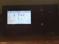
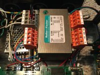
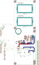
I have modified PCB and schematic and did some changes to the source code (a good start is also the source code provided by another fellow user on the Elektor board). I also wrote a Python GUI for the remote supply, so, if you like you can use ist as a stand-alone power supply. I also made a LTSpice model for the analog part of the RemoteSupply, so one can setup different voltages. Some pics attached.
If you’re interested we can make this a project….
p.s. I stand corrected: only 12-bit ADC/DAC (which, IMHO, is sufficient) and a RPi with 7” touch display, no Arduino. Unit runs completely standalone. Display can be omitted and RPi accessed/controlled via VNC…
Attachments
-
 5928684D-1FE9-4048-96F0-A84181AEE519.jpeg385 KB · Views: 167
 -
 17877E37-8045-4808-B98E-071172BFF09F.jpeg280.7 KB · Views: 176
 -
 F001FFC6-8D34-4E4F-B4D6-7A4C40CE678E.jpeg555.8 KB · Views: 169
 -
 BF794112-87BB-4106-BB28-1D79654418D6.jpeg558.1 KB · Views: 170
 -
 7426266E-B656-479F-BF87-75EAC29F5D1C.jpeg443 KB · Views: 177
 -
General schematics.pdf106.2 KB · Views: 166
-
Distributionboard_schematics.pdf45.8 KB · Views: 152
-
remote_supply.sch.pdf88 KB · Views: 138
-
Semiconductor Adapter_schematics.pdf15.3 KB · Views: 130
-
TubeCurveTracerDescription.pdf4.2 MB · Views: 182
Last edited:
Analog Devices has a HV switching chip for this -- LT3751. It's a $10 part but TSSOP with exposed pad. Otherwise see Jim Williams (RIP) notes on HV switchers. https://www.analog.com/media/en/technical-documentation/application-notes/AN118fb.pdf Analog's "slew controlled" switchers eliminate some of the "noise" issues which could be catastrophic for HVI can help with SMPS to provide some of the voltages you need.
Hi v4lve lover,If you need any design input feel free to contact me,
I'm walking around with the idea to build a DC tube tester for a long time, and have schematics and ideas in my head but the practical implementation still requires that i start and get on with it.
I can help with SMPS to provide some of the voltages you need.
I think, that the generation of the high voltage less of a problem, but parts availability will these days dictate the design. In the chip shortage, many of the beautiful chips are just not on stock. And I want to use common available transformers as well, and luckily these are available.
The challenge is, to make the design FCC conform, to pass the FCC/CE test, particular the high voltage confirmation. Its very difficult for example, to find connectors what are spec'ed for >600V, and if, they are bulky and expensive. This is very different from a DIY device, where you dont need to care this, and have all freedom.
I understand those issues. Given that you are dealing with a low volume marked that jacks up the unit price really quickly.
What i would advice, is a 70% product, EG 70% finished 30% to be completed by the customer like the Roetest. So you could say, make boards that are 70% SMD 30% through hole and have the boards assembled in china. Leave the TH soldering and assembly to the customer.
I was thinking of a tester by myself, and i came to the conclusion modularity would be nice. so you can build a tester that suits your needs.
Also you dont want the tester to be computerized. its a nice gimmick but with the speed of technological advances its better to create a fully Analog tester. So just 4 or 5 current and voltage adjustable supplies. And an extra module to measure transconductance. Optional module to do shorts and isolation checks.
You can then mix modules, on a standardized faceplate. So if people are only testing double triodes, they can have double anode /GM measurement circuit instead of G2 supply ect.
As a marked strategy, you would only sell the bare PCB's laser cut front panel and the custom wound SMPS transformers and maybye the panel meters from China. Create a simple PHPBB forum where people can support and organize themselves and moderate it actively.
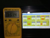
See attached a screen grab from the tester i was working on. My idea was to use a single 24VDC power bus from a standard off the shelf mean well. So you dont have to deal with mains voltage. And the supplies use a standardized mechanical template.
Every supply is current and voltage controlled with CC/CV indication. This is a must for most of the supplies as it protects both the equipment and tubes from damage.
Cheers,
V4Lve
What i would advice, is a 70% product, EG 70% finished 30% to be completed by the customer like the Roetest. So you could say, make boards that are 70% SMD 30% through hole and have the boards assembled in china. Leave the TH soldering and assembly to the customer.
I was thinking of a tester by myself, and i came to the conclusion modularity would be nice. so you can build a tester that suits your needs.
Also you dont want the tester to be computerized. its a nice gimmick but with the speed of technological advances its better to create a fully Analog tester. So just 4 or 5 current and voltage adjustable supplies. And an extra module to measure transconductance. Optional module to do shorts and isolation checks.
You can then mix modules, on a standardized faceplate. So if people are only testing double triodes, they can have double anode /GM measurement circuit instead of G2 supply ect.
As a marked strategy, you would only sell the bare PCB's laser cut front panel and the custom wound SMPS transformers and maybye the panel meters from China. Create a simple PHPBB forum where people can support and organize themselves and moderate it actively.
See attached a screen grab from the tester i was working on. My idea was to use a single 24VDC power bus from a standard off the shelf mean well. So you dont have to deal with mains voltage. And the supplies use a standardized mechanical template.
Every supply is current and voltage controlled with CC/CV indication. This is a must for most of the supplies as it protects both the equipment and tubes from damage.
Cheers,
V4Lve
Attachments
Look interesting. While I would build an adjustable smps also for the high voltage, need a linear regulator afterwards, too. While looking at your schematics, I wonder how the high voltage sensing (and current regulation) is working for the remote supply: In remote_supply.sch.pdf, the high voltage (up to 500V according the remarks in the schematic) comes out of Q6, and the joint of Q6 and R14 goes directly to the Opamp IC4B (LT1078). According to the datasheet of the LT1078, the absolute maximum input voltage is 30V. How can this LT1078 survive the 500V?This is exactly what I have! Powered by a RPi 3B.
I have build and —made upgrades— (hard- and software-wise) of this unit from an old Elektor article. (https://www.elektormagazine.com/lab...emiconductor-curve-tracer#/comments/labs/1527). LOTs of Kudos to Rainer Schuster who’s been an excellent help!
A YT video explaining the unit:
I have modified PCB and schematic and did some changes to the source code (a good start is also the source code provided by another fellow user on the Elektor board). I also wrote a Python GUI for the remote supply, so, if you like you can use ist as a stand-alone power supply. I also made a LTSpice model for the analog part of the RemoteSupply, so one can setup different voltages. Some pics attached.
If you’re interested we can make this a project….
p.s. I stand corrected: only 12-bit ADC/DAC (which, IMHO, is sufficient) and a RPi with 7” touch display, no Arduino. Unit runs completely standalone. Display can be omitted and RPi accessed/controlled via VNC…
I saw in TI application notes, how they put high voltage, over a high omic resistor to an opamp input, what then builds a voltage divider together with the feedback resistor from opamp out to this input. I did not saw from the schematic, how this voltage divider is working, without understanding the opamps internal schematic. I needed some time until I understood these TI app note. But I can not imagine, how the IC4B survive the 500V on its input, because there is no resistor between its input and the HV. Your useing lots of Linear Technology parts, so my guess would be, LT have an app note where they introduce this design, showing how the LT1078 can survive/work with 500V direct to its input pin. Could you give me a link to this app note?
- Home
- Amplifiers
- Tubes / Valves
- is there interest in a new TubeTester?