Dear all,
would there be interest in a (digital) Tube-Tester as a commercial product? To my knowledge, there are now only historical tube testers sold, and a few kits for tube tester. I know this overview of existing (and old) Tube Testers: http://www.jacmusic.com/Tube-testers/Digital-Testers-Compare/FRAMES/COMPARE-INDEX.htm
I am thinking of making a regular product, with FCC test, of such a device. Depend on interest, there could be additional to the test functionality, also a "Tube regenerating function". I have a book from 1943, where 2 German engineers describe the regeneration of death tubes, and there is a small community around the globe what use that technique with some success.
The sales price would be in the range of 500 USD for a simple device, an 1000 USD for the Delux version. What do you think, would there be a market for this? If there is enough interest, I could do a kickstarter.com campaign.
sure, function wise. The big difference is, that the named 3 are sold as kit, the user has to build them by them self, and those do not have a FCC certification. So the user of the 3 kits need to be high voltage experienced.It would all depend on how it compares with the uTracer ($230 - 350), etracer ($850 - 2000) and RoeTest (~$1200+)")
Non of the 3 above support regenerating of tubes (other then supplying the voltages, and at least the uTracer can not supply the required power to regenerate the tubes).
Feature-wise, it should have the same specs and functionality as the etracer, plus the regeneration, and be a finished device with FCC.
I have an etracer, Chris the guy that made it has sold quite a few, even outside electronic geeks its big in audiophile circles. But for a product that doesn't do traces, just a tester, the guitar amp community would love a device that matches pairs or quads maybe. Along with short, gas, emission and gm tests. One thing I like about etracer is you could make your own custom socket panel since the socket series strings just terminate at a row of banana jacks 1-10. I made a panel from 1-12 pins to trace compactrons, Chris didn't go to 12 pins. I like the computer hook up with etracer, you see the curves and you have the data to do matching graphically or in excel at any time later. A device that dumped the data from 4 tubes at once would make matching faster. The etracer has regular software updates. And each etracer comes with a small file that compensates that particular built unit, so it is accurate as unit to unit part values can differ. That file you keep forever. Assembly was two evenings, lots of sockets and ferrite beads! Screw on a fan, a meanwell PS, drop in the motherboard. For the banana jacks I used 6.35 mm quick connects, no solder. And there was one more dupont header to do up. Not a difficult kit.
Last edited:
I'd rather the tester have published communications specs so anyone could write software or log data. My early 1980s Keithley meter speaks GPIB and getting out data is easy. Let's no go the Audio Precision route where the hardware is useless without obsolete versions of Windows and their proprietary software. For reading out numbers and generating plots that could all be done in Python.
sgnAudio I believe a commercial tube tester sold for between $500 and $1000 USD would be a saleable item, it is a very low target price for a quality device.
I have built a few tube testers in my time, after designing and constructing a couple tube/valve curve traces that used a pulse testing method I decided it was often misleading and made tubes look better than they actually are, the cathode often performing better than it would under sustained high power, grid current is often acceptable until the tube runs at significant power for many minutes.
My testers:
https://sites.google.com/view/kenstubetester
https://sites.google.com/view/kens-schematics-2/tube-tester-and-curve-tracer
There is an important difference between a tube tester and a curve tracer.
If I was to build another tester I would:
1/ Use an common Arduino as the main PCB, so easy and cheap to program.
2/ Design 3 x galvanically DC power supplies to be used for B+, Screen, Bias and Filament with serial i/o for data. The DC power supplies would be capable of continuous full power operation, for soak testing, noise testing, thermal drift testing, tube regenerating function etc; 16 bit ADC's with range switching on the current and voltage measurements would be required.
3/ Have provision the use relay switching for the tube sockets as I have found it most satisfactory as it puts everything under software control.
4/ Bluetooth so no wired connection to PC or phone app, this is a safety feature as high voltages and currents are involved.
5/ All firmware and software would be open source so people smarter than myself could enhance it , all including myself could benefit.
6/ The PCB designs would be free to use and modify with schematics and simulations in the public domain.
7/ Provision to plug in a cheap serial POS receipt printer for printing tube test results.
8/ The device should be able to run stand alone without an external computer. If made now it would not run on win15 without some upgrade work!
9/ Calibration verification should be very simple.
BTW within its ratings the same tester with the correct software could also test FET's, bipolar transistors and diodes.
Ken K
sgnAudio I believe a commercial tube tester sold for between $500 and $1000 USD would be a saleable item, it is a very low target price for a quality device.
I have built a few tube testers in my time, after designing and constructing a couple tube/valve curve traces that used a pulse testing method I decided it was often misleading and made tubes look better than they actually are, the cathode often performing better than it would under sustained high power, grid current is often acceptable until the tube runs at significant power for many minutes.
My testers:
https://sites.google.com/view/kenstubetester
https://sites.google.com/view/kens-schematics-2/tube-tester-and-curve-tracer
There is an important difference between a tube tester and a curve tracer.
If I was to build another tester I would:
1/ Use an common Arduino as the main PCB, so easy and cheap to program.
2/ Design 3 x galvanically DC power supplies to be used for B+, Screen, Bias and Filament with serial i/o for data. The DC power supplies would be capable of continuous full power operation, for soak testing, noise testing, thermal drift testing, tube regenerating function etc; 16 bit ADC's with range switching on the current and voltage measurements would be required.
3/ Have provision the use relay switching for the tube sockets as I have found it most satisfactory as it puts everything under software control.
4/ Bluetooth so no wired connection to PC or phone app, this is a safety feature as high voltages and currents are involved.
5/ All firmware and software would be open source so people smarter than myself could enhance it , all including myself could benefit.
6/ The PCB designs would be free to use and modify with schematics and simulations in the public domain.
7/ Provision to plug in a cheap serial POS receipt printer for printing tube test results.
8/ The device should be able to run stand alone without an external computer. If made now it would not run on win15 without some upgrade work!
9/ Calibration verification should be very simple.
BTW within its ratings the same tester with the correct software could also test FET's, bipolar transistors and diodes.
Ken K
Ken K, thank you for the very detailed analysis. I share most points of you.
1. The tester will have its own MCU, to run stand alone. It will have Wifi and BT, and the test results can be seen on a web browser on any Phone, Tablet, PC. So there is no electric connection of the viewing device with the tester, what is a safety feature.2. I am thinking of a modular power supply design: on the main board, there are 4 sockets for 4 power supply boards: the B+ board, the screen board, the bias board and the heater board. Each board have its own voltage and current measurement, and transmit these values to the main board. Be able to deliver continuously the full power is required for the reasons you named, plus the regeneration of tubes. ADC will be 16 bit or 24 bit, and range switching.
3. Relay switching. While several tube tester offer cabling the sockets (what is cheap to produce compared to a relay solution), this approach is unsafe and can not be FCC or CE certified. So a relay array, with 64 relay, is given, to switch any signal/voltage to any pin.
4. Wifi will be offered, to see the results on a Web-browser. I may make the Sigrok interface also work by wifi, to have a second analysis platform.
5. I plan an additional Sigrok interface, so that the Open Source community can continue developing the software. Me, and the 3 shown existing tube tester makers need to make money for a living, and prevent other companies to copy the design. The 3 others make there own closed Software and give the schematic free. I would go the other route, keep the hardware design and make the software open source. The Sigrok part will be Open Source. I may add an Python Interpreter on the MCU, what have access to all measured data and can control the data acquisition, and the website generation, so that users can modify it as needed. Because the modular concept, PCBs can be replaced. I plan to use SMD fine pitch parts, what are not easy for DIY-replace.
6. I have to keep a minimum, to prevent other companies from copy my product. So the schematics and parts of the firmware will not be available public, but the PC software, and the Python code on the MCU are open source.
7. A POS receipt printer is a very interesting idea. I will add this as an option.
8. The device can be stand alone operated, controlled via a Web browser. Additionally, it can be operated by Sigrok.
Hope that would be the best compromise.
I agree with published communication specs. I plan to make a Sigrok open source interface, so that the open source community can modify and extend the Software. Sigrok is an Open Source software package, to control Measurement equipment like Scopes, Multimeters, Logic Analyzers and so on, from a PC. Its cross platform.I'd rather the tester have published communications specs so anyone could write software or log data. My early 1980s Keithley meter speaks GPIB and getting out data is easy. Let's no go the Audio Precision route where the hardware is useless without obsolete versions of Windows and their proprietary software. For reading out numbers and generating plots that could all be done in Python.
SgnAudio we do seem to think alike, as a commercial decision retaining IP on the hardware is a good idea, the Open Source community should be able the update the software as required making the hardware almost future proof. Writing code for a POS serial printer is very easy, one can also get them with a paper cutter to cut off the report, it can be placed in the tube carton with the tube (after it cools). I have found even the cheap ones work quite well, I have a few similar to this one, they seem to last a long time, I've never had one fail.Ken K, thank you for the very detailed analysis. I share most points of you.
1. The tester will have its own MCU, to run stand alone. It will have Wifi and BT, and the test results can be seen on a web browser on any Phone, Tablet, PC. So there is no electric connection of the viewing device with the tester, what is a safety feature.
2. I am thinking of a modular power supply design: on the main board, there are 4 sockets for 4 power supply boards: the B+ board, the screen board, the bias board and the heater board. Each board have its own voltage and current measurement, and transmit these values to the main board. Be able to deliver continuously the full power is required for the reasons you named, plus the regeneration of tubes. ADC will be 16 bit or 24 bit, and range switching.
3. Relay switching. While several tube tester offer cabling the sockets (what is cheap to produce compared to a relay solution), this approach is unsafe and can not be FCC or CE certified. So a relay array, with 64 relay, is given, to switch any signal/voltage to any pin.
4. Wifi will be offered, to see the results on a Web-browser. I may make the Sigrok interface also work by wifi, to have a second analysis platform.
5. I plan an additional Sigrok interface, so that the Open Source community can continue developing the software. Me, and the 3 shown existing tube tester makers need to make money for a living, and prevent other companies to copy the design. The 3 others make there own closed Software and give the schematic free. I would go the other route, keep the hardware design and make the software open source. The Sigrok part will be Open Source. I may add an Python Interpreter on the MCU, what have access to all measured data and can control the data acquisition, and the website generation, so that users can modify it as needed. Because the modular concept, PCBs can be replaced. I plan to use SMD fine pitch parts, what are not easy for DIY-replace.
6. I have to keep a minimum, to prevent other companies from copy my product. So the schematics and parts of the firmware will not be available public, but the PC software, and the Python code on the MCU are open source.
7. A POS receipt printer is a very interesting idea. I will add this as an option.
8. The device can be stand alone operated, controlled via a Web browser. Additionally, it can be operated by Sigrok.
Hope that would be the best compromise.
https://www.aliexpress.com/item/4000089296652.html?spm=a2g0o.productlist.0.0.320263964XCmmY&algo_pvid=c8ec13aa-9239-4754-abd9-fd8e220bc6f2&algo_exp_id=c8ec13aa-9239-4754-abd9-fd8e220bc6f2-11&pdp_ext_f={"sku_id":"10000015440260861"}&pdp_pi=-1;27.72;-1;3.01@salePrice;AUD;search-mainSearch
It is not a bad output device I used one on a past tube tester and intend to fit one to my current design one day.
Relay switching is very cool and a delight to use, it does make a more expensive tester, I do believe many people are willing to pay for quality, it is no good making the product too cheap and going out of business.
All the best with this product the world needs a good new tester.
Ken K
I'm editing this post to say the thermal printers need a low z power supply or they fail to work or print badly.
One of the nice touches of the utracer is that screen and plate supplies are identical, so when testing a double triode both halves can be done simultaneously, and plotted together.
When bulk testing, a way to have one tube heating while one is being tested would save a lot of time. Some sort of toggle between socket A and socket B?
When bulk testing, a way to have one tube heating while one is being tested would save a lot of time. Some sort of toggle between socket A and socket B?
OldHector, good points. The uTracer does not have the relay array, so you see the identical screen and plate supplies as a positive. With the relay array, you can always put both anodes on B+.
About the heating one, while testing the other tube: I had also thought on this. I think its a good feature, particular for people who test a lot. Its just a question, how many sockets are placed. And what tubes you use: Heating multiple 12AX7 or ECC83 is simple, but monsters as the 6C33? Just 1 monster a time.
Do you think, only the heating is required, so no B+ and no screen supply while heating? If so, it would be not difficult.
I bought a few hundred CV4024 (SQ ECC81) thinking there was a market there, sorting them by manufacturer/construction, curve tracing on a uTracer, saving the graphs and data, and then selling them as pairs matched using the graphs, and providing the data. In the end I run the quick test until I get subsequent results in the same ballpark, as a way to be sure the tube is heated and stabilised. It is quite time consuming, taking a few minutes per tube, and then I could not really reap any dividend when I sold them. There is always the P&P costs, and it is not a particularly liquid market (how many people at any one time are looking for a pair of CV4024?).OldHector, good points. The uTracer does not have the relay array, so you see the identical screen and plate supplies as a positive. With the relay array, you can always put both anodes on B+.
About the heating one, while testing the other tube: I had also thought on this. I think its a good feature, particular for people who test a lot. Its just a question, how many sockets are placed. And what tubes you use: Heating multiple 12AX7 or ECC83 is simple, but monsters as the 6C33? Just 1 monster a time.
Do you think, only the heating is required, so no B+ and no screen supply while heating? If so, it would be not difficult.
The issue with the uTracer, that you mentioned, is the pulse heating, but that is easy to solve with an external supply.
I think the people who are in the market for the type of tester you describe would be bulk testing. In which case the tube type stays the same between testing, so I am not convinced that elaborate relay pins selection is necessary. They had relays 70 years ago, but they did not go that way. They used thumbwheels or punch cards. The utracer is just mini banana plugs. The wiring to the sockets is a double loop (like in an AVO) with plenty of graphite beads, so unwanted oscilillations are dealt with, and wiring runs are short and direct.
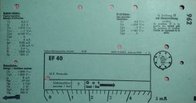
I acquired a Funke W.20, and that has punchcards which are no trouble to use to set up different tubes. Select the card for the tube, push plugs through the holes, and the then it is just to turn the knob through about 8 positions, and all the possible short cominations are tested, and by the time you get to the last setting the tube is heated and the characteristics can be recorded; the characteristics are listed on the card. It has every tube socket you could imagine, but it is big and weighs a ton! Curve tracing is possible but it is a manual operation.
The Funke also has a headphone socket - a useful feature if you need to screen tubes for noise.
Rambling a bit, but I suppose it is horses for courses. A tube supplier has different demands to a hobbyist, and a guitar player is another market. Personally I want to be able to have something that I can service myself, that does not hide the operation of the tube from me (so I have to understand the testing methodology). But a high-end audio connoisseur or guitar player could be different, and a large scale operation might want something fool proof so they can delegate a boring job.
Attachments
Last edited:
Thoughts on a suppressor supply?4 sockets for 4 power supply boards: the B+ board, the screen board, the bias board and the heater board.
A nice feature of etracer is making LT Spice models for a single tube or 2 to n tubes in parallel. For one tube you just save the data file then import it into Derek's program that spits out a Spice model of that exact tube. To create a spice model for let's say three EL 84's hooked in parallel triode strapped. You'd breadboard the 3 tubes together with 100 screen to plate resistors, and heat them from a separate AC supply. Then just bring the grid, cathode and plate leads to the etracer and trace your triple parallel tube as though it were one tube, it doesn't know it three tubes. The etracer not doing the heating. Save the data file then convert it to LT Spice, or print the curves for your triple parallel triode strapped pentode.
- Home
- Amplifiers
- Tubes / Valves
- is there interest in a new TubeTester?