IC4 is at the S side of Q6. The OA sees only a fraction of the 500V through a voltage drop. R17 defines the value for voltage adjusted and R14 for current drawn. Well thought through design. My unit is in service since three years.
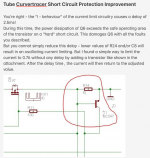
LTSpice model attached. We also added a short circuit protection.
LTSpice model attached. We also added a short circuit protection.
Attachments
Last edited:
Aha, what is labeled as X3-2 + is on GND, while X3-1- is a negative voltage output in respect to schematic-GND. I had overlooked that GND connection of X3-2 +, with this it makes all sense. Thanks for the clarification.IC4 is at the S side of Q6. The OA sees only a fraction of the 500V through a voltage drop. R17 defines the value. Well thought through design. My unit is in service since three years.
LTSpice model attached. We also added a short circuit protection.
One advantage I took from it is the modular design. With the change of two resistors the remote supply serves a wide range of voltages and currents. I have my unit set to supply the following:
A: 0-400V, 0-350mA
G2 (S): 0-400V, 0-50mA
G1 (cg): 0-140V, 0-50mA
H: 0-17V, 0-3.5A
Also since the supplies are separated galvanically it’s easy to supply all kinds of different voltages to a DUT. I did test my EAR completely and did a brief burn-in, while monitoring current draw, with the unit before attaching it to separate PSU.
With the curve export function it’s easy to match tubes.
To change voltages (current) you have to calculate a new value for R17 (R14) —I do simulate with LTSpice— and then change two lines in the source code (hardware.h) and recompile. I have setup QT Creator directly on the RPi and do this on the RPi, takes 2 mins on a 3B…
The forms load in QT Creator and easily modified as well. The Python GUI I wrote is limited to one remote supply board in the moment and was more a POP for me. Works well with a slider for V and A.
In the Case of interest I have a full set of Gerber files for remote supply and distribution board. Original and enhanced version with 5V supply added and the Micro connectors replaced by more common connectors.
In the original design there’s a small glitch adding resistors at MISO on very board. Only 1 required on the distribution board! Otherwise RPi won’t boot up!
Last edited:
I'm asking of the project for the consumer the OP was considering. I've come across some fairly rarish EL34s with low emissions that need rejuvenating and came across this thread. I need a good tube tester as well and not really inclined to building one.
Not a finished product, but a lot of what was said in previous posts:
https://pypsucurvetrace.readthedocs.io
https://pypsucurvetrace.readthedocs.io
- Home
- Amplifiers
- Tubes / Valves
- is there interest in a new TubeTester?