apologies
"What !
I do not think Charles's idea has fallen apart in the slightest"
OK, my apologies, I just got the impression that Charles was "throwing in the towel ", so to speak, about arguing his case.
But I do think there is a problem that needs to be addressed with the two output stages not having matching crossover currents. Their distortions will not match. As I suggested earlier, using Sziklai - CFP output pairs with local feedback in both outputs might address this. Or maybe Hawksford style error correcting outputs. But this does rather go against the grain of reducing feedback.
The dual voice coil speaker approach might help too, since both outputs are driving similar loads, albeit one seeing a low impedance load and the other a high impedance load. (the impedance shift due to the unequal output gains)
Don
smoking-amp said:....On the original thread title: "anybody built a non fdbk ampl?"
I don't really want to read thru all 50 pages to see if someone already came up with this, but how about using current mirrors with gain to build a linear amplifier without feedback. This idea actually works quite well using vacuum tube current mirrors, but has not caught on yet in the incandescent component society.
...
Don B.
Current mirrors with gain have been used in the past (although not mentioned in this thread IIRC). The Blomley output stage comes to mind (around 1970).
The 'problem' is that the output behaves like a current source, while most loudspeakers like to be driven by a voltage source. It is easy to convert the current source to a voltage source by applying feedback from the output, but then it is no non (global) feedback design anymore.
Steven
output impedance fix?
"but then it is no non (global) feedback design anymore" Steve
Yes, I guess there is no getting away from either global feedback or an emitter/source follower to get the output impedance down from a current source.
One other possibility does come to mind though. If one were to just put a load resistor on the current source output to set an impedance level, then put one of those ancient devices called an output transformer after that, to get down to 8 Ohm output. Not too efficient I suppose.
Don
Oh, a small thought on the SPLIF thing. Using the dual voice coil speaker on both outputs, with the open loop output stage gain set a little higher so as to effectively shift the load impedances. One might in theory be able to adjust the sizing of the output transistors according to the shifted loading so as to get matching distortions in each output stage. The open loop output would need the bigger transistors for the higher currents. This is very similar to the technique used in current mirrors with gain, to get linearity. One can also just use a lot of identical transistors in parallel to get size scaling.The global feedback output would be lightly loaded by the high impedance load seen then, so would (or might ? hmmm) have reduced EMF feedback from the speaker.
I guess this technique could also be applied to just a normal speaker with one voice coil too, one just sacrifices some velocity feedback inherent in the dual VC design. Make sure to add a little resistance in series with the open loop output to keep the two stages from dissagreeing with each other violently.
smoking-amp said:(snip)*** Off Topic ****
Was Mikeks article on output stage safe area protection published in EW+WW? which issue?
Don B.
Yes it was published, I dont have the exact dates but I can look it up and email you if you want.
Jan Didden
Re: output impedance fix?
Don,
If you look at the data sheet for the AD844 you will see exactly your idea: the gain stage is an open loop current conveyer (although there is tons of local feedback in current mirrors of course). Then that is followed by an open loop buffer. Now if you can scale this up you have your amplifier!
Jan Didden
smoking-amp said:"but then it is no non (global) feedback design anymore" Steve
Yes, I guess there is no getting away from either global feedback or an emitter/source follower to get the output impedance down from a current source.
One other possibility does come to mind though. If one were to just put a load resistor on the current source output to set an impedance level, then put one of those ancient devices called an output transformer after that, to get down to 8 Ohm output. Not too efficient I suppose.
Don(snip)
Don,
If you look at the data sheet for the AD844 you will see exactly your idea: the gain stage is an open loop current conveyer (although there is tons of local feedback in current mirrors of course). Then that is followed by an open loop buffer. Now if you can scale this up you have your amplifier!
Jan Didden
Hi Jan,
I have to make a trip sometime to the library near here that carries EW+WW to catch up on the last years articles anyway, was just wondering if the article was in there. Thanks anyway!
Looks like an output buffer is the way to go after the current mirrors with gain. My output transformer idea falls apart on closer inspection. Just waists half the power in the load resistor at higher voltages, might as well just use an 8 Ohm load resistor and avoid the xfmr. Either way, 1/2 the output power gets soaked up in the load resistor just to set the output impedance.
I'm curious about your statement of there being a lot of local feedback in the current mirror, I usually think of them as just being predistortion followed by distortion giving a linear result. I guess it depends on how elaborate a current mirror design one uses. I'm working with some vacuum tube current mirrors lately, they look very much like the simplest SS version, but the input device is just a vacuum tube diode. It performs 2/3-power current to voltage conversion, followed by a pentode which does 3/2-power voltage to current conversion. Comes out nice and linear.
More thoughts on the SPLIF idea extensions:
A simple way to alter the voltage gains of the two output stages with respect to each other is to just use a resistive divider on the global feedback output to slightly reduce its drive voltage with respect to the open loop output. Rather than having to use Sziklai-CFP pairs to boost the open loop gain slightly.
The idea of using scaled transistor sizes between the two outputs may be able to solve the distortion mismatch problem (into similarly scaled speaker load impedances), but I think it may be canceling out the isolation of the speaker EMF to global feedback gained by the high impedance load for the global feedback stage.
Smaller output transistors require bigger correction voltages in the feedback for the same current adjustment due to smaller transconductances, making the stage more sensitive to EMF currents. One benefit cancelling the other benefit. So that modified scheme appears to fall apart.
Thinking a little further, with current mirrors on the mind, another scheme comes to mind.
The second open loop output stage should be a complementary current mirror output stage operated by a resistor from the same VAS as the global feedback voltage output stage. This way the open loop current stage can be very linear in relation to the voltage output stage with its global feedback. (probably would want to use separate output crossover biasing networks for the two output stages) Again I would use the dual voice coil speaker to start off, connecting the two outputs to each VC.
The gain of the current output stage would now be adjusted (with a mid band sine wave test signal) until minimum current is drawn from the voltage stage. If the speaker were a true resistor, then the voltage stage output would always just match the load voltage developed by the current stage output, and no current would be drawn from the voltage stage. For the real speaker case, the EMF voltage will match the voltage output stage until the speaker mis-behaves like around a resonance frequency or when reactive. Then the voltage stage supplies corrective currents to bring the speaker EMF in compliance with the drive voltage, close to a velocity servo in effect.
Simplifying to just a normal single VC speaker, should still work, but one loses some of the velocity servo effect since the voltage stage is then matched to the speaker EMF plus the Ohmic VC losses. I guess a listening test would be in order to see if its a worthwhile tradeoff.
Although not really a low feedback design, I think one could call it a feedback only when the speaker is misbehaving design! For a speaker with good impedance characteristics in the most important listening frequency range, it would effectively be zero feedback.
Still, for all the trouble of two output stages, I think it would be worthwhile to just add a few more small signal components to get the full Yundt V-I composite amplifier design. The dual voice coil option being most worthwhile for woofers and sub woofers where the speaker tends to misbehave due to resonances and the velocity servo is useful.
Don B.
(sorry for being so long winded this morning! I probably have run out of ideas for SPLIF modifications at this point anyway.)
small mod. makes very interesting design
The complementary current mirrors as 2nd output stage design, in my previous reply, becomes VERY interesting after a minor change.
The current mirrors can be very linear from input to output, so it makes more sense to connect their inputs (which would just be a couple of moderate value resistors from the voltage takeoff point to the mirror inputs) to the actual voltage stage OUTPUT, rather than to its driver (or VAS) input. The complementary current mirror stage can also be operating in class AB mode without crossover distortion (as long as a load is connected), so can be reasonably efficient and trouble free. (It does need to be thermally drift free however, so maybe some op. amp. DC servo)
This small mod. means the whole 2nd output stage can be added onto any amplifier without even opening the case. (provided separate power supplies are provided for it) For the DIYer, one can just tap into the existing power supplies. Linearity between the two stages is not affected by any crossover distortion issues as long as the original voltage output stage was biased correctly.
A switch removeable sense resistor between the original amplifier voltage output terminal and the speaker is accessable for setting the gain of the current mirror output stage so as to minimize the current draw from the voltage stage under signal conditions (with speaker attached, AC meter on the sense resistor for nulling to a minimum, gain adjustment pot. on the add-on current mirrors unit, test signal input to ampl. provided internally from add on unit or just use a test CD) Either a single or dual voice coil speaker can be driven just by connecting up the outputs appropriately.
This would make an ideal add-on product providing it can be made to work stably with existing speakers. And in the dual voice coil speaker case, should provide close to the same performance as velocity servo systems for use in woofers or sub-woofers.
Hey, when do we go into business guys? 😉 (This idea is hereby declared public knowledge for all. )
)
Oh, and by the way, the Yundt style V-I composite amplifier can be made as an add-on unit for any amplifier as well, but may be more tricky to get stability with its extra feedback loop involved.
Don B.
Oh, Mikek has sent me a copy of his SOA article. Thanks Michael!
The complementary current mirrors as 2nd output stage design, in my previous reply, becomes VERY interesting after a minor change.
The current mirrors can be very linear from input to output, so it makes more sense to connect their inputs (which would just be a couple of moderate value resistors from the voltage takeoff point to the mirror inputs) to the actual voltage stage OUTPUT, rather than to its driver (or VAS) input. The complementary current mirror stage can also be operating in class AB mode without crossover distortion (as long as a load is connected), so can be reasonably efficient and trouble free. (It does need to be thermally drift free however, so maybe some op. amp. DC servo)
This small mod. means the whole 2nd output stage can be added onto any amplifier without even opening the case. (provided separate power supplies are provided for it) For the DIYer, one can just tap into the existing power supplies. Linearity between the two stages is not affected by any crossover distortion issues as long as the original voltage output stage was biased correctly.
A switch removeable sense resistor between the original amplifier voltage output terminal and the speaker is accessable for setting the gain of the current mirror output stage so as to minimize the current draw from the voltage stage under signal conditions (with speaker attached, AC meter on the sense resistor for nulling to a minimum, gain adjustment pot. on the add-on current mirrors unit, test signal input to ampl. provided internally from add on unit or just use a test CD) Either a single or dual voice coil speaker can be driven just by connecting up the outputs appropriately.
This would make an ideal add-on product providing it can be made to work stably with existing speakers. And in the dual voice coil speaker case, should provide close to the same performance as velocity servo systems for use in woofers or sub-woofers.
Hey, when do we go into business guys? 😉 (This idea is hereby declared public knowledge for all.
)Oh, and by the way, the Yundt style V-I composite amplifier can be made as an add-on unit for any amplifier as well, but may be more tricky to get stability with its extra feedback loop involved.
Don B.
Oh, Mikek has sent me a copy of his SOA article. Thanks Michael!
smoking-amp said:Hi Jan,(snip)I'm curious about your statement of there being a lot of local feedback in the current mirror, I usually think of them as just being predistortion followed by distortion giving a linear result. I guess it depends on how elaborate a current mirror design one uses. (snip)
Hi Don,
I will need to ponder your post, am on the road right now.
As for the local feedback of current mirrors, I think that is generally accepted but correct me anyone if necessary). Look at the current gain of the individual transistors, which is used to linearize as you mentioned) the transfer of one element to the other, i.e. 100% of the gain is returned. Thats 100% local feedback.
Later,
Jan
Oops - I missed a point on biasing
I just realized that the complementary current mirrors (with gain) output stage DOES in fact require a precision biasing network for smooth crossover, or has to operate in class A or maybe Ab as a compromise.
Where the top and bottom current sources overlap current around the V=0,I=0 crossover, their gain changes by a factor of 2. This would upset the precision gain setting for nulling current from the voltage amplifier output stage. Nothings ever easy darn-it, but should be do-able with some kind of servo.
Don B.
feedback in current mirrors
Hi Jan,
I am seeing your point about the feedback, the first transistor in a typical current mirror has its base and collector connected together, so is providing feedback from collector to base to make a higher current version of the base - emitter diode. But the strange thing here is that the result is just to make the transistor act like a good diode characteristic. If one were to just put a diode in that spot, it would be hard to find any feedback path.
This is especially the case in the vacuum tube version of the simple current mirror. Just a thermionic diode is used at the input to perform 2/3 - power current to voltage conversion. (with the subsequent output pentode doing 3/2 - power voltage to current conversion.) All current gain in this case comes from simple geometric scaling of the diode size to pentode size. No obvious feedback. A mystery. But then, tubes are mysterious wonders anyway.
Don
By the way, the second output, current sourcing output stage idea, or the Yundt style V-I composite amplifier idea too, could either be adapted to do impedance conversion for tube amplifiers, with the result that their expensive, frequency limited, output transformer could be deleted. Would be hard to convince the incandescent component society that this was still tube sound though.
Re: feedback in current mirrors
Hi Don,
Yeah well, I don't want to start a discussion on THAT! In fact there were others at this forum which, in a discussion whether is was possible at all to built amps with zero fb argued that a current mirror (and an emitter follower) have 100% fb, and that an amp with zero fb was impossible. I think they had a point, but (for once😉 ) I'm not very particular on it.
Jan Didden
smoking-amp said:Hi Jan,
I am seeing your point about the feedback, the first transistor in a typical current mirror has its base and collector connected together, so is providing feedback from collector to base to make a higher current version of the base - emitter diode. But the strange thing here is that the result is just to make the transistor act like a good diode characteristic. If one were to just put a diode in that spot, it would be hard to find any feedback path. [snip]
Hi Don,
Yeah well, I don't want to start a discussion on THAT! In fact there were others at this forum which, in a discussion whether is was possible at all to built amps with zero fb argued that a current mirror (and an emitter follower) have 100% fb, and that an amp with zero fb was impossible. I think they had a point, but (for once😉 ) I'm not very particular on it.
Jan Didden
smoking-amp said:Hi Jan,[snip]Looks like an output buffer is the way to go after the current mirrors with gain. My output transformer idea falls apart on closer inspection. Just waists half the power in the load resistor at higher voltages, might as well just use an 8 Ohm load resistor and avoid the xfmr. Either way, 1/2 the output power gets soaked up in the load resistor just to set the output impedance. [snip]
Don,
I don't follow you. If you have a current source output followed by a transformer, your load/speaker is reflected back to the current source (scaled by the winding ratio of course, squared), so there is I think no need for a seperate Rload on the current source side?
Jan Didden
Jan,
The resistor is to set some kind of output impedance for the case where there is no feedback loop to set it. The current source itself has theoretically infinite output impedance. The transformer can transform this by its impedance ratio, but x * infinity = infinity still. No damping factor that way without the load resistor. I suppose for the real case one could try to transform down from the finite high impedance, but would be sooome transformer with bad frequency response.
Well those guys that wanted to build a no feedback amplifier will just have to learn tube theory I guess.
Don
Would you believe ANOTHER SPLIF idea!
This idea isn't really new, just the method of attack to apply it to an existing amplifier is in essence along the SPLIF theme. Lets disect the old amplifier slightly and make it class H.
Lets say one starts with a conventional global NFB class aB amplifier with 2 or 4 sets of output transistors. Take half those outputs and disconnect them from the rail voltages. Separate the two groups of emitter follower outputs. The still connected group output emitters now drive the center tap point of + and - 5 Volt or so floating power supplies. The + and -5 Volt supplies connect as the new + and - rails for the separated output stage group. The separated group gets a new Vbe bias circuit set for class A biasing, and is driven off the original VAS output. This group then drives the speaker load.
Since both amplifier output sets are driving the same load current (the two output stages are in series as far as the load current is concerned), the VAS predistortion requirements to correct output stage nonlinearity should be somewhat similar for each. So now one ends up with a class A buffer output operating without global NFB. The original global NFB amp is acting as an accurate class H floating power supply for the buffer and even conveniently predistorting out some of the buffer's distortion. Although I guess one could still make the case that speaker EMF feedback (or current actually) is affecting the global feedback. Could cure that, I think, by making both stages class A so the feedback always sees constant current loading, but would really be a hot stove then.
Don
smoking amp,
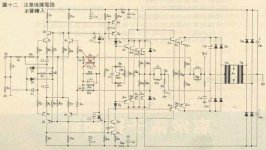
Something like the amplifier below, but then take away the feedback part from the right hand output stage. Right?
Only make very sure that, unlike the amplifier shown, both output stages are perfectly equal and biased in the same way, otherwise the feedback from the left hand amplifier (the one driving the floating supply) will predistort the drive voltage of the right hand amplifier (the one driving the loudspeaker).
The example in the picture is not usable for this without modification since the left hand amplifier is biased in class B (or C) and the right hand amplifier in class A.
Steven
Attachments
Hi Steven,
Yes, exactly, just would need to move the global feedback to the first stage controlling the rails. Looks like a clever implementation of a class H amp. where they were able to use the same input and VAS and Vbe biasing even.
If both stages are "exactly" identical parts and class of operation, then the global feedback would pre-distort out the errors in the second stage I guess, since both stages have the same load currents. Only problem is that the speaker currents still affect the global feedback, due to their still passing thru the first stage, so kind of nulls out the whole point of the SPLIF idea I guess. I'm not sure if running the first stage class A too will help, but it sure waists power then.
Don
smoking-amp said:If both stages are "exactly" identical parts and class of operation, then the global feedback would pre-distort out the errors in the second stage I guess, since both stages have the same load currents. Only problem is that the speaker currents still affect the global feedback, due to their still passing thru the first stage, so kind of nulls out the whole point of the SPLIF idea I guess. I'm not sure if running the first stage class A too will help, but it sure waists power then.
This is the famous Sano (et al) circuit, patent # 4,115,739, the
point of which is to run the output stage in pure class A
efficiently. It is quite far from the SPLIF concept.
Another possible advantage of this (and class H) is that you can use very fast, low voltage output transistors for the low voltage output stage. Because very fast, rugged high voltage devices with large SOA are rather scarce, this gives you the best of two worlds. Of course, the availability of power fets changed that picture.
Jan Didden
Jan Didden
My project alive!
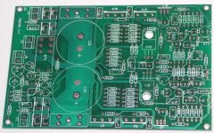
The prototype of amplifier from http://www.diyaudio.com/forums/showthread.php?postid=399274#post399274 is working now.
Bias points are exactly as from PSPICE simulations. There is a 100uF (NP) capacitor in the feedback network, to block DC. The DC at the output is arranged easily and is stable in the range of 0.5 mV.
The current of each power transistors is about 20 – 30 mA.
Here how the pcb looks like:
Attachments
- Status
- Not open for further replies.
- Home
- Amplifiers
- Solid State
- Is there anybody built a non feedback amplifier??