Have no idea in which forum this question belongs, but for the time being the subwoofer forum seems most appropriate.
Is there a DIY technique to measure the BL curve of a woofer?
Is there a DIY technique to measure the BL curve of a woofer?
Not sure what you call BL curve, but BL which is a single number for a given speaker is a parameter found when you measure its Thiele Small parameters.
But BL changes with coil position in many speakers. It's only a single number at a few points and may vary with frequency as well. If this matters of course depends on a whole range of things.
I would like to be able to measure and plot something like this, which is a
.png") clear indicator of a woofers motor linearity vs excursion.
clear indicator of a woofers motor linearity vs excursion.

anyone correct me if I'm wrong:
you might be able to measure input current vs. excursion by applying DC from a lab supply and measure excursion with a paper scale attached to the cone.
the advantage is that you even include non-linearities of suspension.
you might be able to measure input current vs. excursion by applying DC from a lab supply and measure excursion with a paper scale attached to the cone.
the advantage is that you even include non-linearities of suspension.
If we know Q, re, and fs we must then guess that mms changes with frequency, does it, or does it not?I think you need to sweep frequency to get anything meaningful though?
Ok, now I see, you want to check when one winding edge starts leaving the high B area inside the gap (and extending a very small distance beyond it).
Guess finding the real Xmax point will answer the most important part of that question; then you already know you are rolling down downhill.
The DC method suggested by stv on post #5 looks promising to me.
Guess finding the real Xmax point will answer the most important part of that question; then you already know you are rolling down downhill.
The DC method suggested by stv on post #5 looks promising to me.
To avoid any misunderstanding: I a looking for a BL vs X graph, not for X-max as absolute value. The latter is usually known, but the BL vs X curve is much more revealing about the real quality of the motor assembly and the real X(max)lin.
By looking at the Klippel measurements in e.g. Erins Corner, it can be observed the real X-lin is far smaller than the classic VC length-minus PP thickness/2 with most woofers; the Purify woofers being one exception.
By looking at the Klippel measurements in e.g. Erins Corner, it can be observed the real X-lin is far smaller than the classic VC length-minus PP thickness/2 with most woofers; the Purify woofers being one exception.
that gives a solution to the equation: i•Bl(x)=x•Kms(x) ie you cannot separate Bl and Kms. one would need to measure the force to do that. Now if we assume that Mms is constant with x (the surround Mms changes with x for normal (non purifi) surrounds) then you could find Kms(x) by tracking fs(x) since fs is then only a function of Kms. Knowing Kms would allow us to separate Bl(x).anyone correct me if I'm wrong:
you might be able to measure input current vs. excursion by applying DC from a lab supply and measure excursion with a paper scale attached to the cone.
the advantage is that you even include non-linearities of suspension.
Good question. Chance you could actually see it by comparing the output of an accelerometer to the driving signal (acceleration being the derivative, or something like that).
Or just comparing precise voltage output or HD of the precise accelerometer to the driver signal. This is a motional feedback paradigm.
Or looking at a plot of HD (at a given frequency) versus drive signal. There might be a knee in the curve where the BL goes funny. That is a natural test for amps and might be meaningful for drivers... but I've never seen it plotted.
I'm sceptical of the DC test - not much like normal audio/AC operation and might cook your voice coil.
B.
Boden,Is there a DIY technique to measure the BL curve of a woofer?
One could (in theory) DIY duplicate the DUMAX (Drive Unit Measurements At eXcursion) system, which was created around 1995 by David L. Clark (R.I.P.).
Not an easy DIY, obviously- there are a lot of mechanical details in the servo-controlled variable pressure system. The chamber can rotate 360 degrees, mass rings can be added to the cones, different baffles for different size drivers are stored below.
Then there are the laser measurement system, current source driving different functions of applied voltage, etc. etc.
This video explains how it works in detail:
One comment went something like: "air pressure wins over magnetic force 😉 "
All good stuff, gets into operation at around 55 minutes in, block diagram at around 1:27.
Art
Last edited:
I tried this just for fun, with a small monacor mid-woofer, SP-60-4.The DC method suggested by stv on post #5 looks promising to me.
I taped a small paper strip to the dustcap and aligned it with a ruler:

then applied DC current from the lab supply.
Xmax as defined in spec sheet: 2 mm
this corresponds quite well to the measurement:

see results - keep in mind, this was no exact measurement, just a feasibility study!

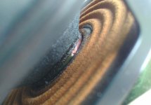
DC resistance is calculated via voltage/amps and temperature of voice coil is calculated via increase in DC resistance (copper +0,4%/°C).
smell was not measured but easily noticeable!
Last edited:
Congratulations.
Measuring beats guessing 1000:1
Voice coil overheating big time because this is DC, no back forth movement to cool it. also a great part of the coil is outside the gap, so no metal nearby makes it even worse.
Notice you took your voice coil to the limit applying "only" 12.7*2.01=meager 25.5W RMS 😱
of course DC RMS, which is DEADLY.
I always laugh at "500W-1000W" speakers ... physically impossible.
Your temperature measurement was very accurate, the real thing, and you got very close to failure , which would have been 170-180 C
Not surprised at the smell, at all.
My benchside test speaker is one of my classic 12" 80W RMS general purpose Guitar speakers (also usable with Bass guitar) and I use it to test anything, including 100W Marshall amps, 300W Bass heads, the works.
Yet it survives for years ... or until a Musician wants to buy that one .... they notice it sounds "better" than new ones .... very reasonable because these are literally "burnt in" he he.
Soft and comfortable like an old shoe, and for the exact same reason, they survive abuse because I let them play freely ... until I notice overcooked Epoxy smell ... which is quite ugly.
Modern commercial voice coils use adhesive coated wire, think "nylon" or similar, which semi-melts when passing DC current at the winding machine ... fast, easy and clean: cheap.
Or alcohol activated adhesive, even weaker.
I still work old style: wire is wound wetted in liquid Epoxy, then hardened with hot air or in an oven.
Slooowww but STRONG.
Last edited:
absolutely!meager 25.5W RMS 😱
of course DC RMS, which is DEADLY.
I did not realize that until I smelled it and then calculated the power, which of course was much higher because of the increased resistance of heated up voice coil.
2 amps through a 4 ohm voicecoil (8 V) resulting in 16 W seemed not too much for a 60W driver ... now I know better, also about power rating!
sorry @Boden for going off topic!
Attachments
using DC the voice coil has very poor cooling. The high power ratings for modern sub drivers are achieved through forced air circulation through the driver (hence the pole vents etc.). If you want to use this method I would recomend only momentry application of the DC with an electronic sensor to quickly read the displacement.
Hi Boden,
have a look at IEC 62458-2011-07: Sound system equipment – Electroacoustical transducers – Measurement of large signal parameters, section 4.2:
4.2 DC large signal
A constant DC voltage or current of fixed magnitude and sufficient duration is applied to the electrical terminals to measure the transducer steady-state response curve. If the transducer is installed in a closed enclosure, a difference between the air pressure inside and outside the enclosure may be used as a static excitation. --> https://www.pollin.de/p/daypower-luftpumpe-lp36-12-12-v-330071
Regards
Heinrich
- Home
- Loudspeakers
- Subwoofers
- Is there a DIY technique to measure the BL curve of a woofer?