Hi everyone,
I'm facing a problem with a new rectifier tube in my 300B SET amp.
The amp is a Raphaelite CSK30 kit I completed some times ago that works wonders with the actual tubes (5Z3P rectifier, WY2p regulators, 6SJ7gt GE drivers and Shuguang 300B/98 Power tubes).
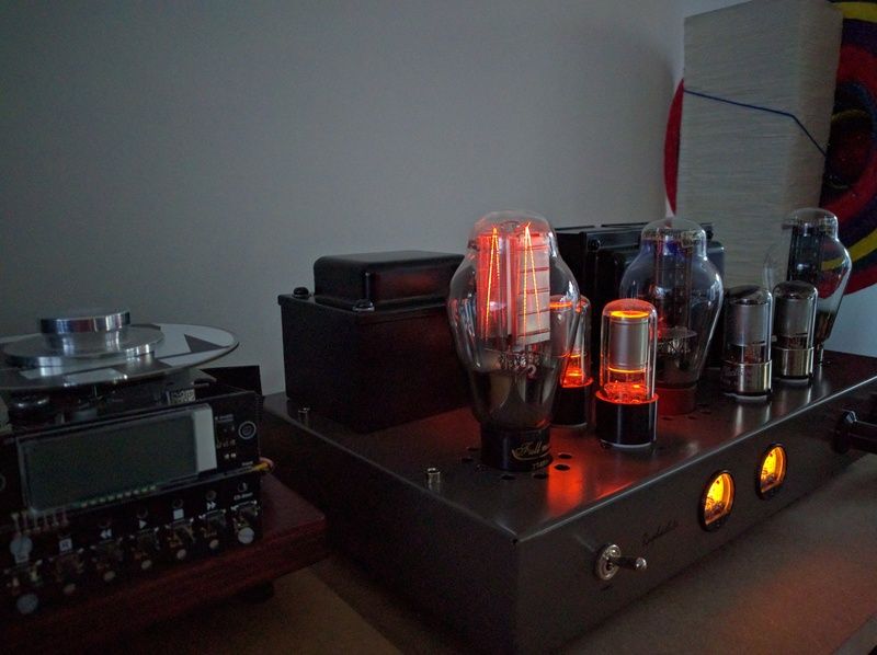
I ordered a Full Music 274b/n mesh plate rectifier and the beast is beautiful with it's visible filaments.
I put the 274b tube in (it's listed as directly compatible with the amp) and turned on the amp:
-at first, no problem, the filaments started glowing normally, as well as the other tubes, no vibrations or strange noises. Playing some music, no problem, great sound......then.....
-after nearly 1min, one of the filaments (not the other) began to glow brighter and brighter 🙁 I switched the amp off and waited for it to cool down.
-I checked everything, from solder joints to unloaded voltage from the transformer and all was normal.
-I tried a second time, this time the tube seemed to behave normally, but after more than 4 minutes, the same filament began to go brighter again, I tried to take a picture of it before it became white, but the fuse blown before I got the time.
So the delay before the filament goes wild is inconsistent.
-I had the time to notice a white dot on the filament.
-The tube is not dead, but I don't want to risk trying again.
I think it's a defective tube, but I may be wrong,
What do you think of it?
Here's a picture of the tube before it begins to go nuts (it's the rear filament, lined with pin 2 and 8)
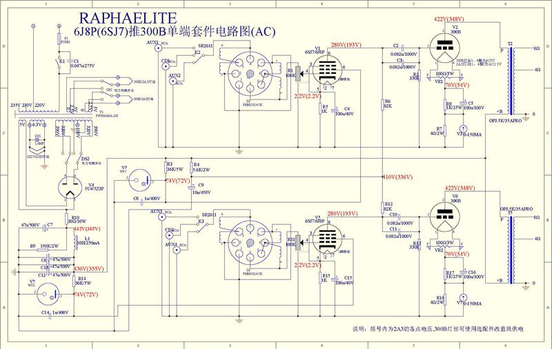
Here's the shematic of the amp
I'm facing a problem with a new rectifier tube in my 300B SET amp.
The amp is a Raphaelite CSK30 kit I completed some times ago that works wonders with the actual tubes (5Z3P rectifier, WY2p regulators, 6SJ7gt GE drivers and Shuguang 300B/98 Power tubes).
I ordered a Full Music 274b/n mesh plate rectifier and the beast is beautiful with it's visible filaments.
I put the 274b tube in (it's listed as directly compatible with the amp) and turned on the amp:
-at first, no problem, the filaments started glowing normally, as well as the other tubes, no vibrations or strange noises. Playing some music, no problem, great sound......then.....
-after nearly 1min, one of the filaments (not the other) began to glow brighter and brighter 🙁 I switched the amp off and waited for it to cool down.
-I checked everything, from solder joints to unloaded voltage from the transformer and all was normal.
-I tried a second time, this time the tube seemed to behave normally, but after more than 4 minutes, the same filament began to go brighter again, I tried to take a picture of it before it became white, but the fuse blown before I got the time.
So the delay before the filament goes wild is inconsistent.
-I had the time to notice a white dot on the filament.
-The tube is not dead, but I don't want to risk trying again.
I think it's a defective tube, but I may be wrong,
What do you think of it?
Here's a picture of the tube before it begins to go nuts (it's the rear filament, lined with pin 2 and 8)
Here's the shematic of the amp
Replace with 2 1n4007 diodes and be happy!
The 274 seems broken. In the meantime you can reinstall the 5z3p
The 274 seems broken. In the meantime you can reinstall the 5z3p
Interesting (and a beautiful valve as you say).
It would appear to be a problem with the valve... and just a thought... could the dim (normal) side actually be the faulty part and the overheating side the one that is passing all the current ?
If it all works OK with the original parts then it does seem odds on favourite the new valve is faulty. I assume its being used within its ratings (current) ?
Interesting (and a beautiful valve as you say).
It would appear to be a problem with the valve... and just a thought... could the dim (normal) side actually be the faulty part and the overheating side the one that is passing all the current ?
Clever 😉 that may be exactly what's going on...
If it all works OK with the original parts then it does seem odds on favourite the new valve is faulty. I assume its being used within its ratings (current) ?
The 300B are biased at 65mA, but I don't know how much current is drained from the rectifier, I suppose it's within tolerances as the 274B is explicitly given as drop off replacement for the 5Z3P, and the amp worked no problem till then.
How can I check the current drained from the rectifier? looking at the voltage drop through the 30R 10W resistance maybe?
Do you have an oscilloscope?
If this is the case, measure the waveform at the cathode of the rectifier, where it joins to the resistor. There, you must see a sinusoidal rectified of equal amplitude. If not, it may be that the switch in the transformer's secondary be defective, overloading one side of the double diode.
Also, try removing that switch, it appears to be useless.
Do you have an oscilloscope?
If this is the case, measure the waveform at the cathode of the rectifier, where it joins to the resistor. There, you must see a sinusoidal rectified of equal amplitude. If not, it may be that the switch in the transformer's secondary be defective, overloading one side of the double diode.
Also, try removing that switch, it appears to be useless.
I have a scope, so I can check that 🙂
That's right that I don't need the switch since I don't plan on using 2A3 tubes in a forthcoming future.
Put res. 1 ohm after chock and measure U on it. Current I = U/1ohm.
I'll try the shunt resistor also
thanks a lot for those advises, I'll let you know how it turns out.
Good luck. Keep us posted, and if you can, paste a photo of the 'scope screen, so we can help better.
Good luck. Keep us posted, and if you can, paste a photo of the 'scope screen, so we can help better.
I will, thank you so much 🙂
The 300B are biased at 65mA, but I don't know how much current is drained from the rectifier, I suppose it's within tolerances as the 274B is explicitly given as drop off replacement for the 5Z3P .............
That is well within the ratings of the 274B.
If you add two identical resistors putting one in series with each anode then you should be able to see very similar volt drops across each. If one is doing all the work then that shows a problem with the other half of the device.
I would think two 10 ohm 1 or 2 watt carbons would be fine as a test.
I seriously doubt of the switch. If it has one section defective (Not good contact), then the other not only becomes the other section overloaded, but as the current flows unbalanced between sections, the transformer also becomes saturated as a DC current flows across its secondary, making things worse.I would think two 10 ohm 1 or 2 watt carbons would be fine as a test.
The same can occur if wiring, socket or the tube itself is defective. But I believe more in the switch, as the guy say that the trouble appears some minutes from powering on the unit. Then, if the switch is carbonized and no true contact, then the time to start the fault is timed by the grade of non good contact inside it. This is because I suggested him to remove the switch.
Bakelite appliances are very dangerous when high voltages are present, almost two times fired them completely.
I seriously doubt of the switch...
Hi Osvaldo 🙂
Switch ? who mentioned the switch 😉
Observe the schematic in the first post, there is a switch for change the secondary voltage appearing at the rectifier's plate. If on of its sections is in doubt...
Hey, when you have a minute to loss, please give me a hand with my post in the LT forum ;-D
Hey, when you have a minute to loss, please give me a hand with my post in the LT forum ;-D
Last edited:
If the switch were faulty it could give a similar proposed fault scenario... but we haven't touched the switch here... just swapping the valve from original to this 274 type.
(I think I might know the answer to your LT question 🙂)
(I think I might know the answer to your LT question 🙂)
(I think I might know the answer to your LT question 🙂)
Of course, no doubt at all.
Whoo so much posts 🙂
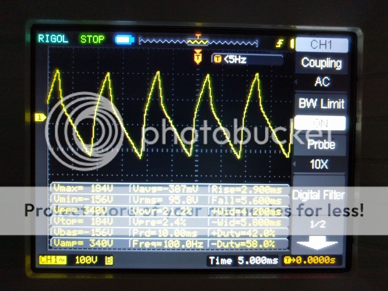
Well I've taken measurements with the scope, probe on the rectifier (5Z3P) pin 8 (where the 30r 10w res connects) and ground clip well.... on the ground star.
Here what I get.
Well I've taken measurements with the scope, probe on the rectifier (5Z3P) pin 8 (where the 30r 10w res connects) and ground clip well.... on the ground star.
Here what I get.
The 274 filaments are all lit (within each plate we see it lit, both up-and-down) so we can rule out that a part of a filament is shorted to itself. That leaves the switch contacts to/from 1/2 of the secondary being open, or the 1/2 of the secondary being open (busted wire inside the transformer, or the outside lead wire). The same could be caused by a very, very bad solder joint, which would become very hot due to the resistance (it would probably be arcing, 390VAC is 551.5 Volts peak). If 1/2 of the filament did not have any emission coating, that would would also cause the problem. In any case, all the above causes would make this a 1/2 wave power supply, not a full wave supply.
I will have another post later, because there is more to this story, even if you solve all the above.
It has to do with the ratings of the 274 versus the 5U4 / 5Z3P. They are not the same.
I will have another post later, because there is more to this story, even if you solve all the above.
It has to do with the ratings of the 274 versus the 5U4 / 5Z3P. They are not the same.
The WE 274A is struggling in your circuit. The 274A maximum capacitance rating for the first filter is 4uF, at near maximum voltage of 450VAC, and 150 mA current.
You have a 40 uF first filter cap (10 times the 4 uF rating). Even at 390VAC, it is not going to work reliably into 40uF. Another problem is the 150mA maximum DC current of the 274.
The 2 300Bs operate at 352V and 70 mA (close to one of WE recommendations). 140 mA
The150k bleeder at 440V is drawing 2.9 mA. That is 1.3 W into a 2W resistor (hot). 2.9 mA
The 2 36k regulator resistors, drop 356V @ 9.9 mA. (3.5W each in 5W resistors, hot). 19.8 mA
The driver tubes each draw 2.2 mA. 4.4 mA
That is a total of 167.1 mA, far too much for a 274 and 40 uF first filter cap.
The 5U4 and 5Z3 / 5Z3P are rated for 225mA into 32uF. Even for those more husky tubes, anything greater than 40uF requires greater than 75 Ohm impedance from each 1/2 of the Secondary. My next posting will talk about the secondary impedance.
The secondary impedance is firstly the DC resistance of each 1/2 of the secondary, and also the primary DC resistance, (which is transformed up due to turns ratio). i.e. 10 Ohms primary DCR on a 120VAC winding becomes 32.5 Ohms on a 390VAC 1/2 secondary. After the DC resistances, the secondary (pun intended) impedance factors are the core losses, and the coupling losses of the transformer. All these factors comprise the series impedance of the secondary winding.
75 Ohms DC resistance 1/2 secondary at 140 mA DC would drop 10.5 VDC. But the Peak current required to get 140 mA DC is much larger, because the rectifier only conducts for a
portion of the 1/2 sine (Alternation). So the resultant drop is much more than 10.5 VDC.
This can become a losing battle to get more output voltage at high current, so an ever more robust rectifier would be required, that can work with a lower secondary impedance.
Using an even higher secondary voltage from a transformer with a higher secondary impedance can also solve one problem, but creates new problems. First, there will be more heating of the transformer due to the losses that create the higher secondary impedance.
When the amp is turned on, which tube warms up first, the rectifier or the output tubes?
They probably have similar warm up times, since they are direct heated filaments, not
indirect heating with a cathode.
But If the rectifier warms up quicker, or the output tubes become weak or fail, the high voltage
will surge to a higher voltage. How bad could it get?
The peak voltage is Root of 2 times higher than the RMS (1.414 times higher).
390 Vrms x 1.414 = 551.5 V peak. The rectifiers will be subjected to 2 times 551.5V = 1,103V reverse. This is OK for a 1500V peak reverse vacuum tube rectifier.
There was a post in this thread recommending 1N4007 solid state rectifier diodes in your amplifier. That might not be a good idea here. First, the tube rectifier may be dropping 30 to 50V or so. But the 1N4007 will only drop a volt or two. So there will be more B+ voltage to all the circuits, and more stress and heating in each of them.
Even more important, the diodes do not have a warm up time. So, we will have 1,103V reverse on the 1N4007 diodes that are only rated for 1,000V (not 1500V of the tube rectifiers).
- Status
- Not open for further replies.
- Home
- Amplifiers
- Tubes / Valves
- Is my 274b/n defective