If the motor strength lacks behind the other parameters, response should be affected.
However, I assume there is a quality check at AE before putting a driver in the box.
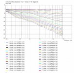
Polar with rollback:
However, I assume there is a quality check at AE before putting a driver in the box.
Polar with rollback:
Attachments
Last edited:
Camplo,
I've forgotten what are your design choice for the way using the 15" ? Bass reflex?
If so you could still make it closed box and use a Linkwitz Transform. You'll probably loose on some criteria ( absolute spl if you need to help bass output) and it may sound different than a reflex box but it could be a way to proceed on your build and see once completed if you need or not to change for another model/type of loading.
EQed closed is most probably superior SQ wise... SPL will still be plenty in home environment...
//
//
Hi TNT,
Well it depend from preference about the SQ. I myself prefer closed but in some case it can sound 'constricted' vs a good ported design and can be problematic if the system is hold pushed for long period ( heat). It's always a compromise.
Camplo's needs are a bit differents than typical domestic use as they'll be used as monitors for works and his design criteria target are not usual or neither is the use ( can run up to 10 hours long in a row in some sessions). That said as he plan to use nearfield that shouldn't be an issue or a minor one, i agree.
Last edited:
TNT, you had these in mind?
I happen to own 4 pcs 🙂
In boxes now but pining for some action.
//
If the motor strength lacks behind the other parameters, response should be affected.
However, I assume there is a quality check at AE before putting a driver in the box.
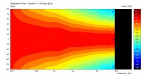
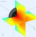
Polar with rollback:
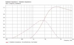
This is much better than the native SWH profile but what about radiation impedance?
"Sound Quality"- pretty nebulous term.I guess one way of looking at it is....I can adjust qts.....but how should I feel about the Motor strength? If the motor strength truly is at 75% of spec....what does that mean in the terms of Sound Quality?
Less motor strength than specified would result in a bit more low frequency and less high frequency output for a given voltage input.
A 25% Bl reduction wouldn't amount to much change in frequency response.
Seems more likely the "16 ohm" voice coil, rather than motor strength is the problem.
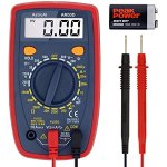
Seems your DATS Re varies by about 10-15% depending on your test,
have you got a battery for your VOM to determine what the actual DCR of your drivers are, compared to the specified value?
If the motor strength lacks behind the other parameters, response should be affected.
However, I assume there is a quality check at AE before putting a driver in the box.
Polar with rollback:
I had two AE drivers fail on me in one year😡
Wow, that's really bad.
What year was the production and what did AE do about it (if anything)?
What year was the production and what did AE do about it (if anything)?
I've been thinking lately… Mitchba uses a TMM configuration which is known for its problems of center to center spacing regarding the tweeter, versus the bottom woofer...yet he seems to care not... One of the reasons why I moved away from using a larger horn was the idea of the ability to get proper quarter wave length spacing between the tweeter and the mid… If I were to let go of that and focus on using the largest horn I could I might be able to cross directly to a large 18 or a pair of 18s
And get that 1960's sound that seems to be eluding you 😉If I were to let go of that and focus on using the largest horn I could I might be able to cross directly to a large 18 or a pair of 18s
That's a really confusing statement… Considering there's a bunch of really bad contemporary designs, and a bunch of really good vintage designs… Also there's a bunch of vintage designs plagued with coloration whether on purpose or coincidence… And the contemporary designs usually aim for a very low THD… Where does that leave me?
I've been thinking lately… Mitchba uses a TMM configuration which is known for its problems of center to center spacing regarding the tweeter, versus the bottom woofer...yet he seems to care not... One of the reasons why I moved away from using a larger horn was the idea of the ability to get proper quarter wave length spacing between the tweeter and the mid… If I were to let go of that and focus on using the largest horn I could I might be able to cross directly to a large 18 or a pair of 18s
Yes, I have not had any issues with this setup either measurement or listening wise. Even across my 6ft x 2ft couch area in a 9ft equilateral triangle. No matter where I sit on the couch, nice smooth frequency and timing response. Official Rythmik Audio Subwoofer thread | Page 1834 | AVS Forum
I am making full use of DSP using steep slope, linear phase digital crossovers (46 Hz and 630 Hz), magnitude correction, CD horn comp, and overall excess phase correction to take care of non-minimum phase low frequency room reflections. I don't correct for excess phase at higher frequencies so the cd and waveguide can do its thang.
camplo, if you can get a bigger horn that would be cool. I have been looking as well, but nothing really pops out other than the KPT-402-MF mid-bass Tractrix Horn from Klipsch... Good luck!
I happen to own 4 pcs 🙂
In boxes now but pining for some action.
//
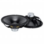
It's the Neo version of the MB15X301 which I recently recommended to krivium.
The corrugated curved cone has been used by RCF for decades.
My vintage drivers have the same type of cone, only about 40-60% lighter (see attachment).
The N301 and X301 still tend to have a rising response due to increasing efficiency with frequency, albeit to a much lesser extent due to the heavier cones.
And here's the bridge to my previous post on (attenuation in) compression drivers.
Moreover, this touches on a discussion earlier in this thread about energy storage (in woofers).
Now, some people may first want to (re)read this excellent post by Tom Danley.
Apart from the phase shift that's inherent to mass-controlled woofers with 'flat' response, there's also an implicit efficiency loss and the incorrect replication of the waveshape of the input signal as byproducts, similar to the 'attenuation' in my previous post.
"To make a driver like this have "flat response", we must roll off the voltage response 6 dB per octave, one pole.
This is done by having a much larger amount of mass or weaker motor such that above some point velocity control is lost and then with increasing frequency, the velocity falls 6 dB oct. It is this range, where the velocity falls 6 dB /oct that one has flat response.
Electrically, this speaker looks like and acts like an R/C filter, the R is the coil R+the amplifier source R and the C is the moving mass of the speaker reflected through the motor, which looks/acts like a capacitor.
Since the moving part is the C, it is the voltage across it (the voltage/velocity output) which falls 6 dB/oct, which is cancelled out by the changing radiation resistance and now gives flat response."
Definition of a R/C filter:
"The simplest RC circuit consists of a resistor and a charged capacitor connected to one another in a single loop, without an external voltage source. Once the circuit is closed, the capacitor (the heavy cone reflected through the motor, in our example) begins to discharge its stored energy through the resistor. The voltage across the capacitor, which is time-dependent, can be found by using Kirchhoff's current law. The current through the resistor must be equal in magnitude (but opposite in sign) to the time derivative of the accumulated charge on the capacitor.
Attachments

Last edited:
And here's the post, including a quote from an old interview with Joachim Gerhard, that started a heated debate.
The woofer characteristics that Joachim refers to match perfectly with Tom Danley's explanation from the previous post.
The woofer characteristics that Joachim refers to match perfectly with Tom Danley's explanation from the previous post.
This is much better than the native SWH profile but what about radiation impedance?
There's room for some improvement in this respect. The horns (simulated by Don) should effectively load the driver from about 920 Hz. Probably just enough for a powerful 1" driver and a crossover frequency of around 900 Hz.
Attachments
Last edited:
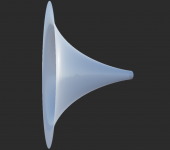
...If I were to let go of that and focus on using the largest horn I could I might be able to cross directly to a large 18 or a pair of 18s
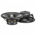
This monster should facilitate a crossover between 300 and 350 Hz.
It's almost 50 cm deep and Ø = 71.5 cm.
Attachments

- Home
- Loudspeakers
- Multi-Way
- Is it possible to cover the whole spectrum, high SPL, low distortion with a 2-way?