
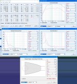
I don't know exactly what the humps are residing far out....(middle impulse) how could it have another reverberation, so far out, after resting at linear for a period...
The bottom impulse, is a sealed enclosure of ~280liters qtc ~0.3
The bottom impulse, is a sealed enclosure of ~280liters qtc ~0.3
Attachments

Last edited:
Alright GM.....you win the TL design contest...doesn't hurt my feelings that you, out of all people were the only people to participate lol! Not one bit. I'm glad you and some others were able to sway me towards the TL enclosure...though I believe sealed is equally desirable and with the idea of multiple subs, an easy reality...but, I like how this is turning out, so...
I will likely repeat your formula for the 15m.... tomorrow...which is today, I've just not slept. Also I am going to begin 3d modelling for the 18h+...but GM or anyone....if you were to give me a sketch of how one would fit a tapered TL into a box with any type of geometrical sense...I'd appreciate it. I may be over thinking it but, we shall see.
I will likely repeat your formula for the 15m.... tomorrow...which is today, I've just not slept. Also I am going to begin 3d modelling for the 18h+...but GM or anyone....if you were to give me a sketch of how one would fit a tapered TL into a box with any type of geometrical sense...I'd appreciate it. I may be over thinking it but, we shall see.
Attachments
Beats me, AFAIK I've never seen an impulse response of a well damped [stuffed] speaker, much less my type of TL alignment, just know they sound 'heart attack' fast like a compression horn or my corner loaded ~14 Hz tuned Altec 515B 'subs' with 500 Hz/2nd order XOs.
GM
GM
Some observations...
Attachments

Last edited:
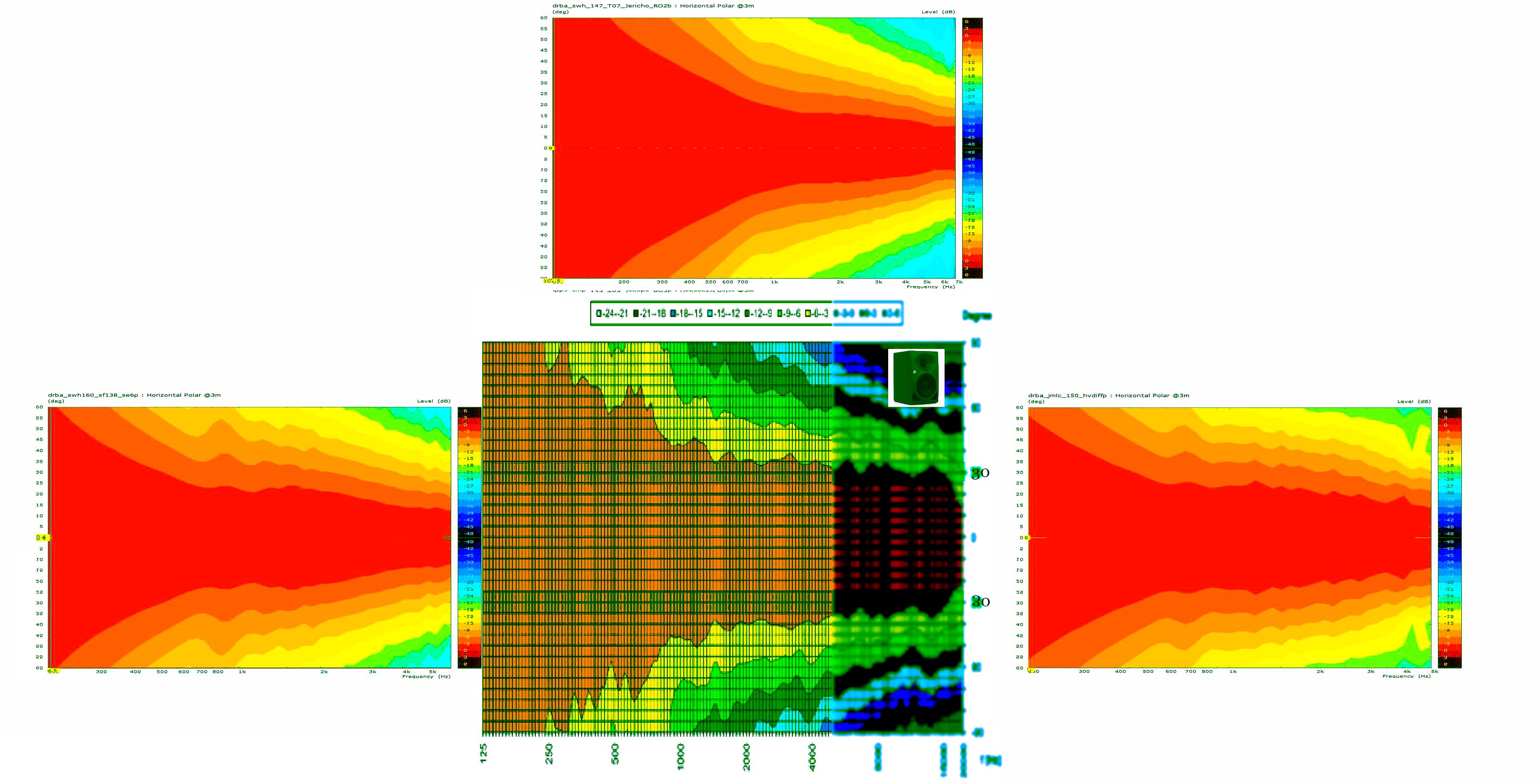
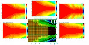
Thats what you expect for all speakers in this kind of configuration with a crossover that high.
Wavelength at 1.7k is 20cm so we are trying to get the 2nd source within 5 cm Center to center to avoid this issue.
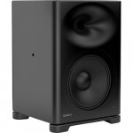
most studio monitors suffer from this issue. Genelec just isn't hiding it at all
Exhibit A. Beaming
The prime territory for SQ is dead on axis, generally. If I was doing some EQ work, I wouldn't want to hear any augmentation of the signal. Thats how I want to work. If I had of designed my build differently and found this out later, I would of been very unhappy lol. Very.
Attachments
Last edited:
You are comparing the step response of an individual driver to those of multiway speakers. Unless the multiway speakers have been time aligned and phase matched the step response cannot possibly look like a single driver.Welt, comparing the step to that of some others...I have no idea what it means lol
What you are seeing is the relative timing and polarity of the different drivers in a multiway speaker.
It can help you see if the drivers are wired in phase or out of phase and how closely they are time aligned.
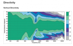
That is a vertical directivity plot and the glitch would be better described as lobing, due to the fact that the drivers are not coincident but vertically spaced apart. Unavoidable in a speaker of that design and is no real issue unless you plan on listening on a different vertical axis than it was designed for, or you like jumping up and down when mixing 🙂Exhibit A. Beaming
The prime territory for SQ is dead on axis, generally. If I was doing some EQ work, I wouldn't want to hear any augmentation of the signal. Thats how I want to work. If I had of designed my build differently and found this out later, I would of been very unhappy lol. Very.
If you end up crossing at 200 or 300Hz that sort of mismatch shouldn't be an issue.
Undamped resonances/reflections from the enclosure. Hornresp tends to make those sort of things look worse than they will be in reality.I don't know exactly what the humps are residing far out....(middle impulse) how could it have another reverberation, so far out, after resting at linear for a period...
The bottom impulse, is a sealed enclosure of ~280liters qtc ~0.3
That is a vertical directivity plot and the glitch would be better described as lobing, due to the fact that the drivers are not coincident but vertically spaced apart. Unavoidable in a speaker of that design and is no real issue unless you plan on listening on a different vertical axis than it was designed for, or you like jumping up and down when mixing 🙂
If you end up crossing at 200 or 300Hz that sort of mismatch shouldn't be an issue.
LOL good point but the reason why those pictures excite me is because I was criticized for the narrow polar of horns we are working on, and even though I stated that critical listening usually happens within 15 degrees of dead axis anyway.... only a few understood....and then I see this speaker, a very common looking speaker with a very "common" flaw....that attempts to create a wider sweet spot but in actuality it is still limited to 15 degrees......So I'm just thinking...if I had of sacrificed aspects of my design in order to "be like the others" to achieve this "wide polar" turns out prime listening territory is in a small window no different than the beaming in the horns I've chose.
- why?If you end up crossing at 200 or 300Hz that sort of mismatch shouldn't be an issue.
- what happens as you lower the crossover...less banding or does the band move lower or both...Unavoidable in a speaker of that design
Last edited:
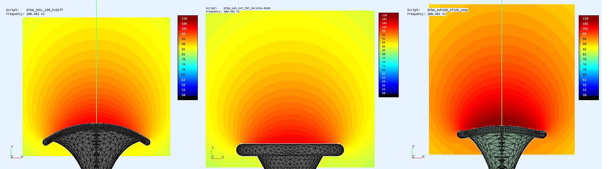
Undamped resonances/reflections from the enclosure. Hornresp tends to make those sort of things look worse than they will be in reality.
Oh, and thank you...thats good to know!
LOL good point but the reason why those pictures excite me is because I was criticized for the narrow polar of horns we are working on, and even though I stated that critical listening usually happens within 15 degrees of dead axis anyway.... only a few understood....and then I see this speaker, a very common looking speaker with a very "common" flaw....that attempts to create a wider sweet spot but in actuality it is still limited to 15 degrees......So I'm just thinking...if I had of sacrificed aspects of my design in order to "be like the others" to achieve this "wide polar" turns out prime listening territory is in a small window no different than the beaming in the horns I've chose.
Horizontal response is more important in general than vertical as there is more horizontal movement when listening than vertical and most times when there is more than one person listening they are horizontally apart rather than vertically.
One of the main reasons for the idea of constant directivity is that there will be a wider sweet spot of correct sound and that any reflections that return will likely have a very similar spectrum. As the sound you hear is an integration of the direct and reflected up to a certain point having the reflections changed in spectrum from the direct sound causes colouration.
There is much research that shows that a flat and smooth anechoic on axis response together with a smooth offaxis response is preferred by most people in blind tests.
You may be able to get a good response and deal with the downsides of directivity that increases sharply with frequency. Most research suggests that you would prefer something else if given the choice in a blind test though 😉
- why?
Distance between the centre of the drivers vs frequency. The longer wavelength of the lower frequency means that the drivers can be spaced further apart without vertical lobing. It is the reason why putting a normal studio speaker sideways on the bridge is a bad idea, you swap the horizontal and vertical directivities around.
If the centre of the drivers are within 1/4 wavelength of each other at the crossover point they should sum together well. The further you move them apart the more lobes you get. This is what happens in an MTM it is hard to bring that distance down enough without lowering the tweeter crossover to a point where it is not happy operating.
I think that's answered above- what happens as you lower the crossover...less banding or does the band move lower or both...
No problem 🙂Oh, and thank you...thats good to know!
This thread has been very interesting and brought up a huge amount of information and ideas and has inspired me to get back to building some horns.
There is a bit of a theme that I pick up on where you are striving for the best of everything individually. That is like having a soccer team full of stars. They don't always play well together and are often beaten by a team that looks worse on paper but can play together.
All the ideas need to work together to achieve the end result.
All the ideas need to work together to achieve the end result.
All the parts need to be able to do many things well in order to actualize that dream. If they work together well past that point, is the responsibility of the coach....and thats about where I am right now searching for information about crossover implementation. I think the challenge of matching a woofer to a horn is a tailoring of the decay. If I could see an impulse of the HF drivers it would say a lot. Good point thanks for bringing that up =).
If you are going active, suck it see on the crossover is quite easy.All the parts need to be able to do many things well in order to actualize that dream. If they work together well past that point, is the responsibility of the coach....and thats about where I am right now searching for information about crossover implementation. I think the challenge of matching a woofer to a horn is a tailoring of the decay. If I could see an impulse of the HF drivers it would say a lot. Good point thanks for bringing that up =).
I'm not sure I understand the tailoring of the decay or what you want to see in the HF drivers impulse ?
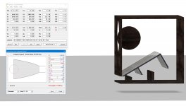
I'm pretty confident in this design, it is a compromise to the original but I played with Horn resp and it seems making the design more of a full taper or somewhere in between, resulted in very similar results or equally desirable. I need to take time and try to measure the new line length, in a general way, to make sure I hit a minimum length, to ensure I keep or only slightly lower, original tuning.
33.75" Tall 32" wide 32.5" Depth. Not bad.
Attachments
Last edited:
If you are going active, suck it see on the crossover is quite easy.
I'm not sure I understand the tailoring of the decay or what you want to see in the HF drivers impulse ?
I was thinking it would give some idea of the characteristics of the driver, I'm not really too worried about it....I am sorta fancied by the idea of creating a MTM, even though the drivers aren't the same, somehow it could work I guess, and even if it was set as a 3way because the xover point is so low, MTM would still work.....I think?
I would suggest that camplo should focus on the round Jericho or this one:
https://www.diyaudio.com/forums/mul...m-spl-low-distortion-2-a-495.html#post6010045
I am not sure what was meant with biradial but my drafts shown had a rectangular mouth/shape.
You did tell me....
An MTM with the 18"s sounds very tempting, I admit.
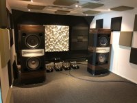
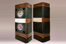
This is Ocean Way's ripoff of JBL's Project K2-S9500.
Instead of the 2" (475) driver in the JBL, Ocean Way apparently opted for the 1" TAD TD-2001 and 2x TAD 15".
Attachments
Last edited:
- Home
- Loudspeakers
- Multi-Way
- Is it possible to cover the whole spectrum, high SPL, low distortion with a 2-way?