oh...guess I'll put it back then...
SO we do all that work and then ruin it with a filter that induces group delay. So my idea was bury the xover a little under 100hz to continue the trend of avoiding the area "before our hearing acuity improves enough". I was reading that certain configurations of xover result in less group delay...my go to is always the LW48db xD...looking at the sim of this...the group delay is just destroyed no matter where I put the crossover lol!
SO we do all that work and then ruin it with a filter that induces group delay. So my idea was bury the xover a little under 100hz to continue the trend of avoiding the area "before our hearing acuity improves enough". I was reading that certain configurations of xover result in less group delay...my go to is always the LW48db xD...looking at the sim of this...the group delay is just destroyed no matter where I put the crossover lol!
Last edited:
The box in #5313 is quite narrow band. How does this mate to the "chosen" horn as as a 2-way?
//
//
A parabolic (Par) flare should be used when simulating a rectangular cross-sectional area horn segment having two parallel straight sides and two sloping straight sides. That is, where the area varies linearly with axial length.
The box in #5313 is quite narrow band. How does this mate to the "chosen" horn as as a 2-way?
//
The 18H+ is being used as a sub. 15m will be under the horn.
A parabolic (Par) flare should be used when simulating a rectangular cross-sectional area horn segment having two parallel straight sides and two sloping straight sides. That is, where the area varies linearly with axial length.
👍
We can call it a 2-ways with stereo subs if you'd like lol
I haven't asked any off the wall questions a while have I?
In the spirit of the MTM, Docali and DonK! have we simulated any bi-radials that can load as low as our big horns? Something that would be useful for a MTM design? I think this deserves some exploration if you guys are up for it.
I haven't asked any off the wall questions a while have I?
In the spirit of the MTM, Docali and DonK! have we simulated any bi-radials that can load as low as our big horns? Something that would be useful for a MTM design? I think this deserves some exploration if you guys are up for it.
Last edited:
On second thought, I’m just delirious and should go to sleep. I am looking forward to seeing the horn we agreed on =)
Hi GM:
Thanks for that. This is my first look at this type of enclosure and I'm enjoying the exploration. I thought I had to enter a known value of Fr but I see from playing with your model that HR calculates the lbs of polyfill needed to get the Fr entered and the achievable Fr range with polyfill is 100 ++ which is what Camplo needs to get his response. Except for the size, these things are almost too good to be true.
And David clued me in to use of F9 key to export SPL data from the Tline wizard so I can see a real IR.
Welt, I don't know how to use VituixCAD...thats obviously not the correct impulse/step responses.....
Attachments
Last edited:
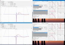
RIght, its not. Sorry I didn't get back to you sooner. Here is what I have:
This a normal IR but inverted.
Now let's figure out what you did wrong!
In HR, did you F9 in the wizard power screeen to export the SPL as a text file?
In Vituix mainscreen after clicking crossover, your schematic should just be a wire from the generator symbol to the driver symbol.
In Vituix mainscreen after clicking driver, to the right of the the bold "frequency response", use the browse button to get to HR export directory and select the file you exported earlier.
You should now see the same FR as you had in HR in the SPL window.
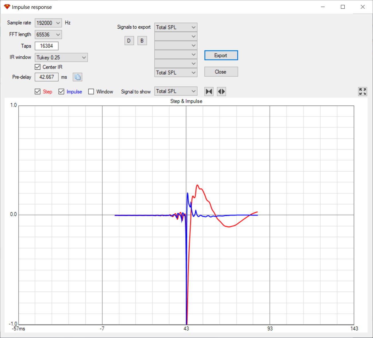
If so, then selecting Impulse Response from the View drop down should show you the IR I show here.
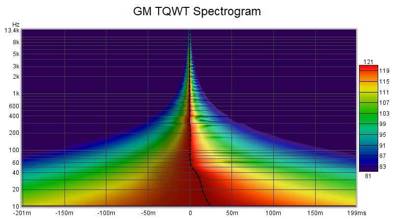
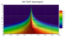
If you export that from Vituix, you can import it to REW as a .wav and see IR spectrum, which looks like
This a normal IR but inverted.
Now let's figure out what you did wrong!
In HR, did you F9 in the wizard power screeen to export the SPL as a text file?
In Vituix mainscreen after clicking crossover, your schematic should just be a wire from the generator symbol to the driver symbol.
In Vituix mainscreen after clicking driver, to the right of the the bold "frequency response", use the browse button to get to HR export directory and select the file you exported earlier.
You should now see the same FR as you had in HR in the SPL window.
If so, then selecting Impulse Response from the View drop down should show you the IR I show here.
If you export that from Vituix, you can import it to REW as a .wav and see IR spectrum, which looks like
Attachments
Last edited:
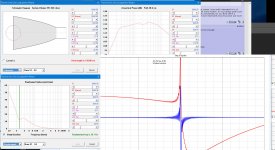
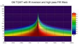
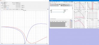
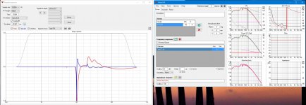
If I do some trace arithmetic in REW to model FIR filtering, I get this, which is what I mean by too good to be true:
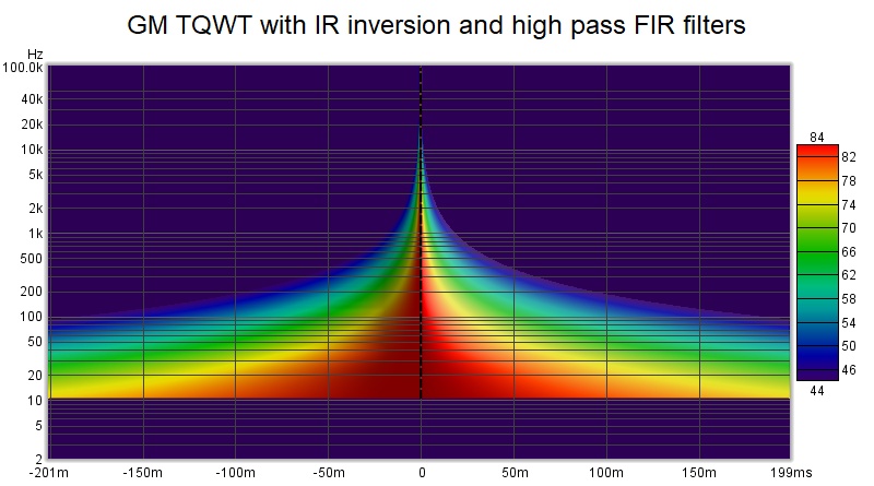
I took the IR exported first from HR and then from Vituix and inverted it with REW "1/A". Then I did A*B where A was the original IR and B was the 1/A result. This produced a flat line as expected. Impulse inversion EQs the response perfectly flat. However that is too much EQ, so its necessary to convolve in a bandpass filter that limits the EQ. I had a room response curve already prepped with a high pass at 20 Hz and a slight downward tilt at 100 Hz and used that. You would likely want a low pass filter at/around 100 Hz but it seems to me you could go higher, perhaps high enough to not need the TD15Ms.
If doing this with measurement instead of a simulation, the pictures wouldn't be so clean and there would be choices to make about how much smoothing and gating to use on the measurement before IR inversion. A program like DRC can do the IR inversion and windowing with more sophistication to produce a filter with less ringing, I see some of that in the IR of final predicted result.
Attachments
Last edited:
We can call it a 2-ways with stereo subs if you'd like lol
I'm easily fooled but not that easily fooled lol
I don't think I'd have to try very hard...its a matter of perspective so its apples and oranges lol
This is only slightly unfair, several people have suggested that I cross straight to the 18" and leave the 15 out of the equation....but that would really make a MTM with the 18" the better choice...if I cross to the 18" or even a MTM in with 2 way xover....you could not argue that not a true iteration of the epitomy of what I originally intended to design....and even though I may or may not go that way...I've stated several times that it was possible...I just felt like at the time that the sacrifice of spreading the spectrum into 3 paths would equate into the best final sound quality....and I still pretty much feel that way...so who wins now?
An MTM with the 18"s sounds very tempting, I admit.
OK heres a good question...when I wondered about the possibilities of a mtm using different woofers... I seen it suggested several times that 2.5 way was possible with different woofers...but how does a 2.5way configured in a mtm configuration with a 18h+ and 15M sound? How does that even make sense?
but since I think more like you, than caring to be the person whos "right"....I'm not that easily fooled either lol!...getting me to admit the obvious...I'll never lol!Sub-bass sounds are the deep, low- register pitched pitches approximately below 60 Hz (C2 in scientific pitch notation) and extending downward to include the lowest frequency humans can hear, assumed at about 20 Hz
This is only slightly unfair, several people have suggested that I cross straight to the 18" and leave the 15 out of the equation....but that would really make a MTM with the 18" the better choice...if I cross to the 18" or even a MTM in with 2 way xover....you could not argue that not a true iteration of the epitomy of what I originally intended to design....and even though I may or may not go that way...I've stated several times that it was possible...I just felt like at the time that the sacrifice of spreading the spectrum into 3 paths would equate into the best final sound quality....and I still pretty much feel that way...so who wins now?
An MTM with the 18"s sounds very tempting, I admit.
OK heres a good question...when I wondered about the possibilities of a mtm using different woofers... I seen it suggested several times that 2.5 way was possible with different woofers...but how does a 2.5way configured in a mtm configuration with a 18h+ and 15M sound? How does that even make sense?
Last edited:
....
A woofer for the bottom can be found. The question is, how is a woofer that is going to be easily responsible from 30hz to ~1000hz going to behave? ....
?
Hi, TNT how far back is that quote? We've been modelling horns with intent to cross at 200hz no higher than 300hz for a while now. The AXi2050 kind of changed the possibilities. Ro808 also posted, not long ago, a successful 300hz xover with a radian and a Be diaphragm!
RIght, its not. Sorry I didn't get back to you sooner. Here is what I have:

This a normal IR but inverted.
Now let's figure out what you did wrong!
In HR, did you F9 in the wizard power screeen to export the SPL as a text file?
In Vituix mainscreen after clicking crossover, your schematic should just be a wire from the generator symbol to the driver symbol.
In Vituix mainscreen after clicking driver, to the right of the the bold "frequency response", use the browse button to get to HR export directory and select the file you exported earlier.
You should now see the same FR as you had in HR in the SPL window.
If so, then selecting Impulse Response from the View drop down should show you the IR I show here.
If you export that from Vituix, you can import it to REW as a .wav and see IR spectrum, which looks like

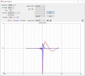
So I made it this far, sorry but I'm completely green to this app, I need to learn it more....for example I didn't know I needed to connect wires in the crossover to make it show a FR....so now I've added that step, this is the impulse I get...I'm sure some other setting is off...some setting that I don't know about with my....=/
Attachments
That looks like it should but you are zoomed way in. Zoom out and you will see the entire thing
>< button
>< button
Ok, ty so much for helping with that! If I could only figure out how to get the impulse to be "right side up"
This response looks strange....I'm not 100% on how to translate it...is it ringing?
This response looks strange....I'm not 100% on how to translate it...is it ringing?
Attachments
Last edited:
have you tried inverting the polarity? as in simply reversing the connections to the driver your testing?If I could only figure out how to get the impulse to be "right side up"
have you tried inverting the polarity? as in simply reversing the connections to the driver your testing?
That was my first thought, I just didn't figure out how to...I know photoshop though lol
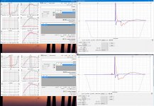
Can I get some wise eyes on these impulse's please? I can't say that I fully educated how to interpret...I do understand some but it would be nice to hear the experienced opinion.
In my opinion they both look ok...the strength of the qts is obvious...one has much more decay than they other...one has more over shoot than the other...step response is still little foggy for me but obviously one has more bass response than the other.
Attachments
Last edited:
- Home
- Loudspeakers
- Multi-Way
- Is it possible to cover the whole spectrum, high SPL, low distortion with a 2-way?