Someone else with more knowledge than me I'm sure could answer your question better, but since no one is trying I'll chime in. We discussed this many pages ago sort of, but the way I understand it, the angle of the horn walls at the frequency in question is the issue. A Tractrix has fairly parallel walls at the throat (where high frequencies launch so to speak) so it has narrow directivity at those high frequencies. A constant directivity horn like an oblate spheroidal is wider angle right from the throat so wider directivity there. A larger Tractrix horn profile will have to stay narrower longer in order to keep the profile right if that makes sense. An OS waveguide would suffer less . Just look at a large Tractrix, that throat is so long. Even at the point where it's 3" in diameter the walls are fairly parallel, yielding narrow dispersion at the wavelengths loaded at 3" area. In a smaller Tractrix at 3" diameter the walls may be flared significantly. Think about it like a garden hose spray nozzle, with small wavelengths squirting from the throat and lower frequencies squirting from the mouth. wavelength launched from a given spot of the horn correlates with the horns area at that point.
I understand this is an idiots guide and it would be an honor to have someone explain to me too exactly what's wrong with my analogy.
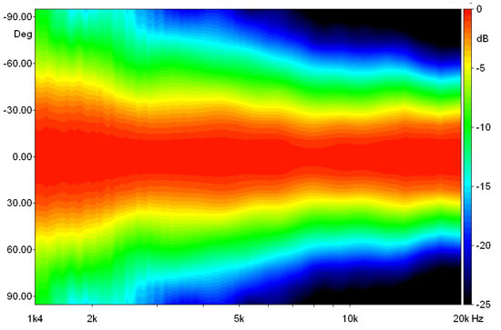
An important aspect (of a Tractrix horn) is the change of the wavefront shape with frequency.
For this reason, a deep Tractrix (used for low-midrange) will beam considerably at high frequencies, whereas a short Tractrix may still provide decent coverage. This is particularly true for elliptical Tractrix horns, like the FaitalPro STH-100:
Looks good Mark, despite the wind.
The HF950 is an intriguing horn, it could use a bigger mouth to reduce the ripple.
Thanks Ro, I think Peter designed a really good box given it's objectives...as powerful and as clean, that can still be put on a stick by one person.
I like the PM60 version a little better sonically...the xt1464 works for me I guess. But I do think the 90 degree version with the HF950 is more practical for PA...I just leave them set up that way now.
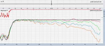
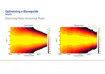
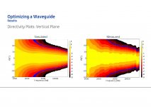
This morning, before the wind rose (and because test setup still in place) I reran the PM90.
It's the first plot below.
I found it interesting that the worst ripple was in the cone section (100-650Hz). (rcf mb12n351's)
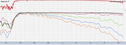
So for contrast, I quickly set up one of my modular builds that I often listen to indoors. It has a single ported 12"rcf mb12n405 which is in its own box and covers the same low/mid passband as the PM90/60s. Top was the same bms coax but on a xt1464 instead, and in its own box too.
Second plot below.
I find it doubly interesting that the low/mid ripple matched fairly closely, a single ported 405 vs dual horn loaded 351s. Need to explore this....
Wind was coming on quick, you can see its presence down low in the second modular plot.
So I only grabbed OA, 15, 30, 45, and 60 degrees for each...
Oh, Is there any software that would let me turn these magnitude traces into the polar plots you like guys have been showing? Like in your immediately previous post?
Attachments
Hi Mark thank you!
Your comment is spot on with what i like about this box, the syntripp and Dsl products i have in mind.
Light loud clear with controled directivity.
About the polar map maybe vituix could help? I think there is direct link with Rew ( i don't use it for now but have read the manual and i think it could do it. Otherwise send me a pm maybe i can help in near future)- newborn son eat time !).
Last edited:
Mark, those responses look good! Wrt to Polar Maps, I don't know if Earl still offers this or not: GedLee LLC
Thanks Ro, I think Peter designed a really good box given it's objectives...as powerful and as clean, that can still be put on a stick by one person.
I like the PM60 version a little better sonically...the xt1464 works for me I guess. But I do think the 90 degree version with the HF950 is more practical for PA...I just leave them set up that way now.
This morning, before the wind rose (and because test setup still in place) I reran the PM90.
It's the first plot below.
I found it interesting that the worst ripple was in the cone section (100-650Hz). (rcf mb12n351's)
So for contrast, I quickly set up one of my modular builds that I often listen to indoors. It has a single ported 12"rcf mb12n405 which is in its own box and covers the same low/mid passband as the PM90/60s. Top was the same bms coax but on a xt1464 instead, and in its own box too.
Second plot below.
I find it doubly interesting that the low/mid ripple matched fairly closely, a single ported 405 vs dual horn loaded 351s. Need to explore this....
Wind was coming on quick, you can see its presence down low in the second modular plot.
So I only grabbed OA, 15, 30, 45, and 60 degrees for each...
Oh, Is there any software that would let me turn these magnitude traces into the polar plots you like guys have been showing? Like in your immediately previous post?
ARTA is one possibility:
http://www.artalabs.hr/images/directivity-sonogram.gif
R&D Stories: Genelec 8351 Acoustically Coaxial SAM System | audioXpress
The figure 8 seems agree with your comment.
Oh, I've forget to mention that the conventional non-coaxial configuration is a poor performer in this test, so considering it as low distortion design is nonsense 🙄
Hi Mark thank you!
Your comment is spot on with what i like about this box, the syntripp and Dsl products i have in mind.
Light loud clear with controled directivity.
About the polar map maybe vituix could help? I think there is direct link with Rew ( i don't use it for now but have read the manual and i think it could do it. Otherwise send me a pm maybe i can help in near future)- newborn son eat time !).
Hi Krivium, first things first... CONGRATS on newborn son !!!
Nothing in life can compare, except maybe daughter 🙂
Glad the comments/plots helped.
I see I stupidly left out the dB scale....the gradations are 3 dB....
Here's a little more info PM 90 vs synergy... mid/low sensitivity.
syn is 60x40 (44" width with secondary flare)
2.83 v on PM90 cones = 103.1 dB 1m
2.83 v on syn (same cones) = 105.3dB 1m
power handling should be same i think
Oh, btw, I realize neither of these fit thread title do they? Whole spectrum, that is....
Sorry, but they ain't the first two, now are they 😉
I'll move any more comments over to the syn thread....
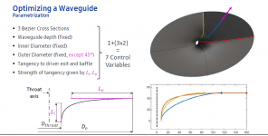
Years ago, WHGeiger proposed to use Bezier Curves to design waveguides, which wasn't greeted with great enthusiasm.
It looks like somebody stole his idea.
This basically shows how the M2 waveguide was designed, even though it looks different.
It looks like somebody stole his idea.
This basically shows how the M2 waveguide was designed, even though it looks different.
Attachments
Last edited:
Bezier curves are just a mathematical means (one of many) of how to construct curves of arbitrary and smooth enough shapes. There's nothing special about them regarding horns whatsoever. They are convenient and easy to work with - that's the reason they are often used for various occasions when you need to get smoothly from one point to another with something else than a straight line. It's an obvious choice if one wants to optimize some shape by chaging the countour in easily defined way - a Bezier cubic is really the most simple solution one could come up with. Not "optimal" in any global sense however. It's just a shape, one of many possible, limited by its own constraints.
cubic-bezier.com
cubic-bezier.com
Last edited:
1) If you want to optimize driver loading at low frequencies use a Salmon horn with 0<=T<1 and annul driver reactance.
2) If not using room boundaries to extend the horn, increased mouth curvature is still required.
3) If you also want to mitigate beaming at higher frequencies, then introduce VIR acoustic lens into the wave front pathway.
N.B.:
VIR - Variable Index of Refraction.
CIR - Constant Index of Refraction
WHG
Thank you for this Whg

Sorry, I don't follow. I've been using Bezier curves for decades, i.a. to generate a simulated air traffic, smoothly changing velocity vectors, etc. They are great for these tasks - extremely handy. For horns, why not, but let's not call it a "horn type" - it is not. You can get almost any shape with these curves, including OSWG or anything else 🙂
Last edited:
It starts to look somewhat familiar.
However, this waveguide is developed for professional cinema, instead of 'monitoring'.
Therefore it's optimized for mid- and far-field coverage.
However, this waveguide is developed for professional cinema, instead of 'monitoring'.
Therefore it's optimized for mid- and far-field coverage.
Attachments
-
 Waveguide Design_Small_Pagina_6.jpg262.2 KB · Views: 223
 -
 Waveguide Design_Small_Pagina_5.jpg264.9 KB · Views: 476
 -
 Waveguide Design_Small_Pagina_4.jpg263.3 KB · Views: 497
 -
 Waveguide Design_Small_Pagina_3.jpg197.3 KB · Views: 504
 -
 Waveguide Design_Small_Pagina_2.jpg394.6 KB · Views: 481
 -
 Waveguide Design_Small_Pagina_1.jpg201.9 KB · Views: 506
 -
 Waveguide Design_Small_Pagina_7.jpg264.1 KB · Views: 201
Would you really want to look at this all the time? 😀
(It could also remind an ex-girlfriend as far as I can tell...)
(It could also remind an ex-girlfriend as far as I can tell...)
Last edited:
Bezier curves are just a mathematical means (one of many) of how to construct curves of arbitrary and smooth enough shapes. There's nothing special about them regarding horns whatsoever. They are convenient and easy to work with - that's the reason they are often used for various occasions when you need to get smoothly from one point to another with something else than a straight line. It's an obvious choice if one wants to optimize some shape by chaging the countour in easily defined way - a Bezier cubic is really the most simple solution one could come up with. Not "optimal" in any global sense however. It's just a shape, one of many possible, limited by its own constraints.
I am a minimalist, so I appreciate it 😛
There's is not a single 'perfect curve'. The best horns are often composed of a combination of these, ATH-4 being an example.
For this specific design process the Bezier is likely convenient.
Would you really want to look at this all the time? 😀
(It could also remind an ex-girlfriend as far as I can tell...)
I prefer 'the lips' to the sight of this rectaguide

It starts to look somewhat familiar.
However, this waveguide is developed for professional cinema, instead of 'monitoring'.
Therefore it's optimized for mid- and far-field coverage.
" optimized for mid- and far-field coverage." by this I assume you mean by how wide the dispersion pattern is....
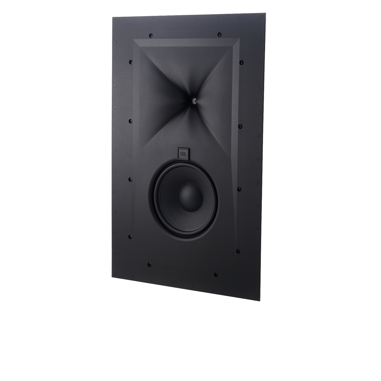
Indeed, those waveguides are wide coverage, similar to this Synthesis In-Wall loudspeaker (100 x 100 deg).
I agree with mabat, the plots in the sheets are not exactly extra-terrestrial.
I agree with mabat, the plots in the sheets are not exactly extra-terrestrial.
Last edited:
Sorry, I don't follow. I've been using Bezier curves for decades, i.a. to generate a simulated air traffic, smoothly changing velocity vectors, etc. They are great for these tasks - extremely handy. For horns, why not, but let's not call it a "horn type" - it is not. You can get almost any shape with these curves, including OSWG or anything else 🙂
I was reading an engineering paper on traffic offramps, and found it funny that the math was basically the same you'd use to make a waveguide 🙂
Basically the engineers found that an important component of reducing traffic was the shape of the offramp; there has to be a smooth transition from freeway to offramp.
- Home
- Loudspeakers
- Multi-Way
- Is it possible to cover the whole spectrum, high SPL, low distortion with a 2-way?