Thank you for your answer.
You answered as i was editing my initial post as it wasn't clear.
Yes i meant using the cone as waveguide. There is imd at work when the cone is moving in driver of this kind and this is the one i'm concerned about.
You answered as i was editing my initial post as it wasn't clear.
Yes i meant using the cone as waveguide. There is imd at work when the cone is moving in driver of this kind and this is the one i'm concerned about.
Bjørn Kolbrek (audioXpress 2008-3):
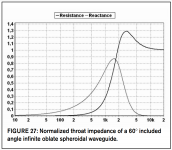
"The OS waveguide does not have a sharp cutoff like the exponential or hyperbolic horns, but it is useful to be able to predict at what frequency the throat impedance of the waveguide becomes too low to be useful. If you set this frequency at the point where the throat resistance is 0.2 times its asymptotic value,
so that the meaning of the cutoff frequency becomes similar to the meaning of the term as used with exponential horns.
The cutoff of the waveguide depends on both the angle and the throat radius. For a low cutoff, a larger throat and/or a smaller angle is required. For example, for a 1″ driver and 60° included angle (θ0 = 30), the cutoff is about 862Hz.
The advantages of the OS waveguide are that it offers improved loading over a conical horn of the same coverage angle, and has about the same directional properties. It also offers a very smooth transition from plane to spherical wave-fronts, which is a good thing, because most drivers produce plane wave-fronts.
The greatest disadvantage of the OS waveguide is that it is not suitable for low-frequency use. Bass and lower midrange horns based on this horn type will run into the same problems as conical horns: the horns become very long and narrow for good loading.
To sum up, the OS waveguide provides excellent directivity control and fairly good loading at frequencies above about 1kHz."
However, I believe you've objected to this disquisition?
Attachments
Last edited:
"It is difficult to optimally design the seating and surface shapes of the coaxial driver. This can lead to poor control of diffraction and colorations. Although the concentric arrangement tendency to cause intermodulation distortions can be alleviated by using a separate woofer, it is usually not possible to sufficiently optimize the midrange cone shape to make the midrange work as a high-performance waveguide for the tweeter. Seating of the midrange cone to the driver chassis and the joint between the tweeter and the midrange typically introduce diffracting edges in the design"
Article by Aki Mäkivirta, Jussi Väisänen, and Ilpo Martikainen during the 137th Audio Engineering Society (AES)
Article by Aki Mäkivirta, Jussi Väisänen, and Ilpo Martikainen during the 137th Audio Engineering Society (AES)
Your drawing of the wavefronts cannot be correct. For it to be correct, the wave would have to move faster at the center than at the edge - not possible.
In fact, it turns out that the true wavefront (not one drawn by hand) cannot have a curvature whose center moves past the origin (thoat) - it can be behind the throat, but not in front of it, i.e. the wave can be flatter, but not more curved than it is at the source.
Nothing was drawn 'by hand' in any of those images.
In fact, these could be generated by just using a keyboard.
"It is difficult to optimally design the seating and surface shapes of the coaxial driver. This can lead to poor control of diffraction and colorations. Although the concentric arrangement tendency to cause intermodulation distortions can be alleviated by using a separate woofer, it is usually not possible to sufficiently optimize the midrange cone shape to make the midrange work as a high-performance waveguide for the tweeter. Seating of the midrange cone to the driver chassis and the joint between the tweeter and the midrange typically introduce diffracting edges in the design"
Article by Aki Mäkivirta, Jussi Väisänen, and Ilpo Martikainen during the 137th Audio Engineering Society (AES)
Mount a large waveguide in the coax' throat and let the woofer 'breath' through slits, located far enough from the throat as to not cause significant interferences.
"To sum up, the OS waveguide provides excellent directivity control and fairly good loading at frequencies above about 1kHz."
However, I believe you've objected to this disquisition?
Just his numbers, I calculate the cutoff to be lower, but then I don't know how Bjorn defines cutoff. Otherwise I agree with what he has stated. Again, just because the "loading" is falling below some point does not mean that it doesn't work well down there. It just means a few more dB of gain in the crossover, that's all.
Nothing was drawn 'by hand' in any of those images.
In fact, these could be generated by just using a keyboard.
Well they can't be correct.
Mount a large waveguide in the coax' throat and let the woofer 'breath' through slits, located far enough from the throat as to not cause significant interferences.
R&D Stories: Genelec 8351 Acoustically Coaxial SAM System | audioXpress
The figure 8 seems agree with your comment.
For those who have no idea wth is 'flare rate', this old RCA has got a very loooooow flare rate.
Not really, it just seems that way 😉; it's initially a conical expansion [fast], then necked down to an expo [medium] flare rate with an undetermined flare frequency, i.e. in the sectoral horn 'family'.
GM
This one wasn't mentioned before, I think.
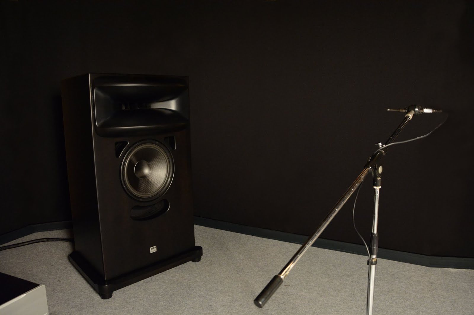
Another classic 2-way that's supposed to meet the criteria of the thread title.
It's a heavyweight, 238kg each!
The horn is about the same size as Joseph Crowe's upcoming ES-300, 70cm width and cut off is 300Hz.
Woofer is an OEM 16" with Carbon Fiber Cone and massive Neo Magnet.
Mms: 70g
Fs: 19Hz
Magnetic Flux: 416000Mx
Comp. driver: TAD TD4001
Bandwidth: 30Hz (-3dB) - 20kHz (0dB)

The Woofer is made by Davis Audio in France😉
I got a quote for a pair to try out and was just shy of 600 euro each. Not to bad considering!
Last edited:
Silverprout, thank you.
I already read this in the past, and just realised it was a quote from the 8531's designer.
I'm not a Genelec afficionados but i must admit i really liked this one when i briefly heard them.
I find funny the last picture in the argicle you linked: a nice control room with Ams/Neve V series console with the 8531... on the metering and oriented on their side! All this technical justification about technology and R&D to perfection... and all this ruined by the worst placement you can find! 🙂
A bit ironic...
Not really, it just seems that way 😉; it's initially a conical expansion [fast], then necked down to an expo [medium] flare rate with an undetermined flare frequency, i.e. in the sectoral horn 'family'.
GM
Yes, I realized this after looking at it again.
WRT flare rate, it turns out I was (partly) wrong:
The flare rate of the horn is defined as:
(rate of change of wave-front area with distance)/(wave-front area).
In a conical horn, the flare rate changes throughout the horn, and the point where propagation changes from reactive to resistive changes with frequency throughout the horn.
In an exponential horn, the flare rate is constant. Here the transition from reactive to resistive wave propagation happens at the same frequency throughout the entire horn. This is the cutoff frequency. There is no gradual transition, no frequency dependent change in propagation type, and that’s why the change is so abrupt.
The Woofer is made by Davis Audio in France😉
I got a quote for a pair to try out and was just shy of 600 euro each. Not to bad considering!
Thanks for the confirmation!
Compared to similar sized high end woofers the price isn't excessive.
I bet the magnet alone is already quite expensive.
And the specs are nice, a light and presumably stiff carbon cone with a very low Fs of 19Hz.
I have to admit that big horn is also becoming more and more attractive each time I see the photos and the CAD drawing.
...or could it be those roundovers unknowingly remind me of the lips of an ex-girlfriend? 😎
Attachments

Last edited:
I know a lot of people like the shallow waveguides, high expansion rate, whatever. I don't care much for them. I've used a few and heard many more. For me they are too direct. I hear the CD diaphragm; I hear the speaker. They work well at low volumes and can sound quite good, almost making me forget the directness of the driver beaming right at me. But once they get loud, they sound "blatty" to me. Like the splatter of a bad trumpet.
By contrast a well designed, well EQed horn that is deeper makes me forget the speaker, I just hear the recording, I hear the music and the space. The point of origin can seem like it's behind the horn, and not in the horn.
That's not a popular view, as these days the shallow horn /waveguide is very much in fashion. I'd only use one if there wasn't enough space for a real horn. Just my personal preference.
You're definitely not alone in this.
I guess you know one is not supposed to listen to OSWGs on-axis?
Actually I found quite a few diffraction horns to sound better than short waveguides.
I guess you know one is not supposed to listen to OSWGs on-axis?
Actually I found quite a few diffraction horns to sound better than short waveguides.
As Before But with VIR Instead of CIR
1) If you want to optimize driver loading at low frequencies use a Salmon horn with 0<=T<1 and annul driver reactance.
2) If not using room boundaries to extend the horn, increased mouth curvature is still required.
3) If you also want to mitigate beaming at higher frequencies, then introduce VIR acoustic lens into the wave front pathway.
N.B.:
VIR - Variable Index of Refraction.
CIR - Constant Index of Refraction
WHG
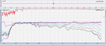
Given the Peter Morris boxes keep getting mentioned, I though I'd post some polars for the PM90 with the bms 4594he/HF950 ..
taken today in a lot more wind than makes for good measurements...but I took them anyway as a sanity/comparison check for today's measurements I was making on the synergy effort...
on axis (black) to 60 degs, 10 deg increments....
my standard tuning...which is make on-axis flat, see how off axis holds up...
(10deg purple looks extra wind suspect..)
LR72 @ 100Hz HPF
Attachments
Last edited:
Looks good Mark, despite the wind.
The HF950 is an intriguing horn, it could use a bigger mouth to reduce the ripple.
The HF950 is an intriguing horn, it could use a bigger mouth to reduce the ripple.
Yes, definitely helps to be off axis. Doesn't fix everything, but it's a good way to use them.I guess you know one is not supposed to listen to OSWGs on-axis?
in your analogy does angle of incidence come into effect ?
I'm afraid the physics is beyond me and I can't say. Just an idiots guide to a practical understanding of why directivity varies by frequency with different horn shapes. I'm really rather disappointed that none of the greats posting here didn't tear my analogy apart, it would have been enlightening. Perhaps I'm onto something after all. 🙂
- Home
- Loudspeakers
- Multi-Way
- Is it possible to cover the whole spectrum, high SPL, low distortion with a 2-way?