A few things -
It's highly likely that you have your pot wired incorrectly. See post #1 for a diagram. That should fix the volume issue.
Make sure the twister board is getting power from the main board at the LED resistor. If it is, then the LEDs will light when inserted properly and the input is switched (unless you've cut some traces and/or used an improper switch).

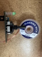
Let's see a couple good photos of that damned Twister. I had a challenge with mine too because I assume way too much and go ahead anyway.
The volume problem seems to be a wiring problem not at the volume control, but the other end for one channel. Take a closer look at the board wiring. One of the channels wirings doesn't look like the other. That is why you have reverse volume for one channel. Did I read that correctly?
The volume problem seems to be a wiring problem not at the volume control, but the other end for one channel. Take a closer look at the board wiring. One of the channels wirings doesn't look like the other. That is why you have reverse volume for one channel. Did I read that correctly?
Last edited:

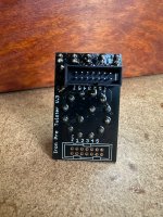
What I notice in the jpg 7879 photo is the possibility that the connection that is close to 'V3' in that photo has come loose. This may be why you are not getting those LED's to light.
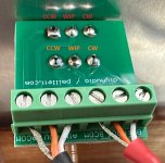
Back to the circuit board problem wiring. Do you see what I am referring to about the CW/WPR/Comm connections? I did the same thing and so that is why I looked for it.
Back to the circuit board problem wiring. Do you see what I am referring to about the CW/WPR/Comm connections? I did the same thing and so that is why I looked for it.
Yes! That is a bad joint! I had put the wrong resistor in and had to desolder. I think I killed that pad in the process. I just tried filling it again and no joy.What I notice in the jpg 7879 photo is the possibility that the connection that is close to 'V3' in that photo has come loose.
Maybe it's recoverable if you scrape away some of the solder mask to expose the trace and get some solder (or a wire) to bridge back to the resistor thru hole?I think I killed that pad in the process. I just tried filling it again and no joy.
I’m going to start back at post #1, check the build guide, and also look for your posts when you had that problem. I remember those. I’ll let you know what I find. Thank you all for the help.Back to the circuit board problem wiring. Do you see what I am referring to about the CW/WPR/Comm connections? I did the same thing and so that is why I looked for it.
Look at jpg7878. The cable with the red heat shrink on it is incorrect. Center red conductor is correct, but the other two are swapped.
I think the build guide photos are like mine although build guide photos don’t seem to agree on R and L in the page 1 duagram. I thought CCWL and CCWR are the grounds at the pot BCOM and ACOM? I thought the white conductor was the IN, red the Wiper/out and shield is GND.Look at jpg7878. The cable with the red heat shrink on it is incorrect. Center red conductor is correct, but the other two are swapped.
If I am wrong, I am not surprised, but, I am only talking about the red heat shrink wire, not both. As stated in the above post, using a meter will make sure that the wires have ended up where they should end up. It is just that I remember that some things were in 'mirror image to each other' and that gets me every time.
Man, I was wrong. I am going to back away for a bit because I do feel that you are very close to getting this corrected. Too many opinions all at once can make things harder, and this is not that. Just a step by step check, and yup you will get there. You are in good hands here. Best news is that you have done nothing that makes for a major repair.
Thank you. Buzzer test worked w continuity as expected. I also tested to the board. It buzzed w knob in all positions, not just mid position. It also buzzed when one lead was on wiper and other on IN on each channel.confirm that pads at pot pcb are correctly traced to pot
buzzer test good enough, put pot in mid position
Hey man, thank you! I hope so. My workmanship on two areas where I desoldered have me concerned though.Man, I was wrong. I am going to back away for a bit because I do feel that you are very close to getting this corrected. Too many opinions all at once can make things harder, and this is not that. Just a step by step check, and yup you will get there. You are in good hands here. Best news is that you have done nothing that makes for a major repair.
Thank you. Buzzer test worked w continuity as expected. I also tested to the board. It buzzed w knob in all positions, not just mid position. It also buzzed when one lead was on wiper and other on IN on each channel.
I wrote pot in mid position, exactly to avoid shorts between wiper and other two pot pins, which is going to happen if pot is in one or other end position
so pot in mid, and buzz will confirm wanted traces
if then you have buzz between pot pins, something is wrong
I forgot to write that you also need to check exactly that, buzz test between pot pins
- Home
- Amplifiers
- Pass Labs
- Iron Pre Essentials Kits For The DIYA Store - Register Your Interest