Yes, I know a way. It was very expensive (initially, anyway) but I got successful result.It's alive! I soldered one SE input for testing and both BAL and SE outputs. Connected the IP to my amp via SE out. Everything seems to work.
Mine is the latest version of Balanced Iron Pre purchased from the diyAudio Store. In addition I opted for Franks Muses volume control built specifically for the balanced Iron Pre.
A couple of observations:
- Muses (default anyway) lowest volume setting is -50dB. Still, I have too much gain on the lowest setting. SE in SE out. The volume level is what I'd describe as lowish normal listening level. Any higher and my wife would raise her eyebrows as a sign to turn it down a notch. Does anyone know if there's a way to mend this either on the IP boards or with the MUSES?
- The sound is fine but not spectacular. Admittedly my expectations are high after a long building period and after reading this whole thread. The IP replaced a DIY passive preamp built with super high quality components. A stepped attenuator and a high quality input switch. No electronics. Still I've long had a feeling the passive pre is the bottleneck in my current system and I did not think the IP would have any problems bettering it. Maybe too early to make comparisons but as for now the IP sounds about on par with the passive pre.
My system is a Magna Hifi modified Sonos connect Ultimo feeding a heavily modded Aqvox DAC which is connected to Iron pre SE in and SE out to a Neurochrome 686 amp. Speakers are Troels Gravesens Faital 3WC-10 .
It's still my first listening hour so the IP might open up. I've experienced this many times with new gear. I also have yet to try both balanced in and balanced out to and from the IP. Now that I know it works I will connect the other inputs and put the lid on.
/Karl
I got rid of the wife and kept the house!
Russellc
The sound is fine but not spectacular.
one thing I forgot to write - probably is worth trying preamp without Iron; simply pull jumpers in between buffer and autoformer, take output signal from pin1 of jumpers
if that brings you benefit, either remove autoformers and install appropriate wire bridge instead, or simply permanently wire output as written above
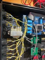
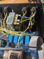
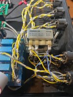
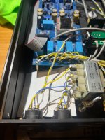
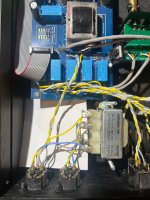
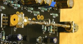
It's a headscratcher for sure. I'm sure I messed up the wiring somewhere along the way. Here are some pics. I attempted to wire it as described by ZM in #2,626.How, exactly, is this wired…?
Photos and schematic please. 🙂
Attachments
was that Gordy's knot functional, prior to implementing additional xformer?
edit: oh, and those pics are so lousy ......
edit: oh, and those pics are so lousy ......

Hi All -
I think (hope) I got back to everyone that had asked when we would have kits back in stock.
Cheers,
Patrick

I think (hope) I got back to everyone that had asked when we would have kits back in stock.
Cheers,
Patrick
Have not tried w/o the second transformer installed but will remove try that tomorrow.
ok, inform here
instead of fiddlindadiddling, why not just building another one?
for second, third, fifth room in Home?

for second, third, fifth room in Home?

Yah, this is my 4th build, so I have time to fiddle. might reconsider replacing the wire with chop sticks. I had time on my hands waiting for parts. Maybe I will shovel snow instead.
Hello Everyone,
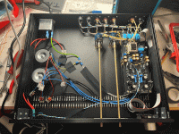
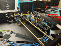
another IronPre is singing. Thanks a lot to Zen Mod, Nelson Pass, Patrick(DiyAudioStore), 6L6, and everyone else on this wonderful Forum! It’s become definitely one of my favorite places on the internet 🙂
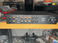
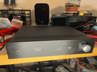
My IronPre still needs some knobs, and maybe I have to tidy up that left side a bit more. But I’m already really happy with the sound of it! It is singing alongside my Aleph J and Pearl 2 builds on some vintage Cheviot HPD’s (last photo). Very fun Preamp and Project!
The build was like already mentioned by 6L6 in his guide very straight forward. Although M1 and M2 do get hot, which worried me a bit during the first power up and setting of the voltages.
The SissySit is next 🙂
All the best from Blackforest Germany
Tobias
The Porn:
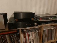



SissySIT is great. My current setup betters it in certain technical aspects I'm sure, but on the other hand I sometimes miss some of the special qualities I used to have with the SS R.3 in place.
Hello,
Just starting a SE build using 2023 v.4 board, essentials and supplemental part (arrived this week).
Two questions.
Do the length of the zener diodes (shorter or longer) reflect the part name (zd1 or zd2) or voltage? Not able to reliably test them (limited equip / knowledge)
Next on the back of the board, for R7 and R8, the pads seem to be joined. Is this correct, and if so i assume its fine to have a solder bridge at that point (not sure how to avoid it). See pic
Please advise, thanks!
Hello Chedma,
try to see what is written on the diodes and identify them that way. You might need a magnifier and a light, since it is really small.
For your second question, you can always have a look at the schematics if you are unsure. But in this case you can also see that both pads are on the same conductor.
- Home
- Amplifiers
- Pass Labs
- Iron Pre Essentials Kits For The DIYA Store - Register Your Interest

