Maybe a separate power supply? If not, it can be used for so many different projects. These chassis are really great. Much better to work with than others that I have tried.
I have some Broskie 12VAC SRPP boards needing a home. Hoping to pack the boards in there with the transformers on top and the tubes poking out. If that doesn't work, will repurpose it for other front-ends because I have been thinking.Beautiful!! What is the little chassis for?
The long term plan is to build a bunch of "front-ends" to play "flavor-o'-the-month" with the F4s. On the dock:
1. the above mentioned tube boards
2. the 2022 DIY front end
3. ZM's iron pre
4. BA-3 gain stage
5. a Broskie noval Aikido front-end (once they come back in stock)
6. an M2x front-end w/ all the daughter cards (will be my first attempt at adapting a circuit, laying out a PCB and sourcing fabrication).

There is a LOT OOS at the Glassware site! I have waited for a long time to get ahold of several circuits from there. Just sold a LV Aikido (4 tube affair) that I don't think will ever come back in play at the site.
another forum member got a response from John B. Looks like it has been a fab issue that might be resolved soon.
https://www.diyaudio.com/community/threads/is-glassware-still-functional.405637/#post-7515188
https://www.diyaudio.com/community/threads/is-glassware-still-functional.405637/#post-7515188
I'm a little bit confused here. (Not so much, at least about it.)
I have learned so far that the XLR connector pinout is as follows:
Pin 1: Ground/Shield
Pin 2: Positive/Hot
Pin 3: Negative/Cold
May I missed something?
There may be other connection standards.
I have learned so far that the XLR connector pinout is as follows:
Pin 1: Ground/Shield
Pin 2: Positive/Hot
Pin 3: Negative/Cold
May I missed something?
There may be other connection standards.
^ ?
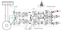
I assume if you ordered the balanced chassis that you'll be building a balanced Iron Pre - You still need a dual gang pot for each channel for balanced. One for (+) and one for (-) ...
Draft of wiring...
View attachment 1235963
^ That is an excellent catch. Pin 1 and Pin 3 are reversed. I'll update ASAP.
Thank you!
Edited to add an updated pic. Apologies for the error.
Thank you!
Edited to add an updated pic. Apologies for the error.
Attachments
Last edited:
I highly appreciate your and others work here.
If I can add a little, I'm very happy!
If I can add a little, I'm very happy!
Something will come of this, if nothing else, at least a toothpick! 😉


^ Looking good!
One of these days, I need to try the "standoff method" for terminals. I have seen it a few times, but never tried it myself. Makes it look elegant.
One of these days, I need to try the "standoff method" for terminals. I have seen it a few times, but never tried it myself. Makes it look elegant.
No, no, I just sanded the end of the brass standoffs to about 1.7 mm to fit the holes, with a drill and a file.
Listening test will be tomorrow, electronics working fine, power supplies are +/- 15.000VDC, DC offset far below 1 mV.
Listening test will be tomorrow, electronics working fine, power supplies are +/- 15.000VDC, DC offset far below 1 mV.
Some day, if I find the right posts to solder through the circuit board, I would want to use wire wrapping for some of the connections.
No, no, I just sanded the end of the brass standoffs to about 1.7 mm to fit the holes, with a drill and a file.
Listening test will be tomorrow, electronics working fine, power supplies are +/- 15.000VDC, DC offset far below 1 mV.

I would like to ask some things:
I've routinely using these IC sockets for almost all of my builds.
So I can change easily all of the low signal semiconductors, even there is an accidental failure, or just for new experience.
So what would be the best choice at the positions J1, J2, J3, J4?
I have plenty (relatively) of them to choose.
Another question, can I test Quasimodo on the fly?
I have sockets on the board for all of the necessary parts, to change quickly them.
And last, but not least, I want to thank everyone for this project, it's one of the best in the history of diyaudio.
I say this without listening to IP yet. 😉
So what would be the best choice at the positions J1, J2, J3, J4?
BL, matched
Can you determine the value of the snubber resistor with the transformer connected to your Iron Pre boards? If that is your question; no. You need to test the transformer by itself.Another question, can I test Quasimodo on the fly?
Can you see if your snubber circuit is working properly in situ? Maybe... You could try scoping the ringing, but if you did get the proper value for the snubber resistor using the Quasimodo... or even without the snubber, I don't know how much difference you would see re: ringing. Me... I would not worry too much.
I admit that I am unsure of your question. So, if I got both of those wrong, my apologies.
it's one of the best in the history of diyaudio.
 No secret how much I like it. Can't wait to hear what you think.
Thank you for posting pictures. It is fun to see some builds.
- Home
- Amplifiers
- Pass Labs
- Iron Pre Essentials Kits For The DIYA Store - Register Your Interest