same logic for implementation
I didn't use TVC - they're not needed for my purposes
AVC is easier to get in same quality (sound wise) and it can reach better SQ than TVC
TVC is logical choice only if you need galvanic isolation between input and output circuits, and if galvanic isolation isn't needed, AVC is logical and better choice
Thank you ZM. I had to ask out of curiosity and it's probably not going to happen even though I've got somewhere a 9335 Sowter TVC..
It's not in use, and am currently fine with a 20K motorized Alps pot in my SE build I should add..
It's not in use, and am currently fine with a 20K motorized Alps pot in my SE build I should add..
what's preventing you of trying it?
I've just checked on Sowter site, they claim it's easy enough load for preceding stage
I wouldn't be surprised at all, in fact - I'm sure it's better sounding option than any resistive attenuator
anyhow, if/when you decide, just buzz and I'll draw little sketch how to
I've just checked on Sowter site, they claim it's easy enough load for preceding stage
I wouldn't be surprised at all, in fact - I'm sure it's better sounding option than any resistive attenuator
anyhow, if/when you decide, just buzz and I'll draw little sketch how to

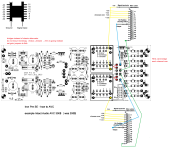
Iron Pre how to wire TVC
whichever gen of pcbs you have ( through hole JFets or smd ones) principle is the same
applies both for @Studley and @geoturbo
though, Tribute is AVC, but having defined IN-GND-OUT points, wiring is the same as shown here for Sowter TVC
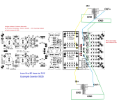
reposted - Iron Pre how to wire Slagle AVC, just in case
whichever gen of pcbs you have ( through hole JFets or smd ones) principle is the same
applies both for @Studley and @geoturbo
though, Tribute is AVC, but having defined IN-GND-OUT points, wiring is the same as shown here for Sowter TVC
reposted - Iron Pre how to wire Slagle AVC, just in case
Attachments
Last edited:


Well you have achieved fame around here and I will soon be sending you money for the Pumpkin, so you need some new goals 🤣
My TKD pots arrived from HiFi Collective. I ordered 20k pair, but messed up and also received a pair of 10k.
Obviously, I intended on using the 20k pair but have seen several using 10k pots..... is there a preference of either one over the other?
Whichever pair I use, I can eventually use the other pair as well.
Thanks for your input,
Russellc
Obviously, I intended on using the 20k pair but have seen several using 10k pots..... is there a preference of either one over the other?
Whichever pair I use, I can eventually use the other pair as well.
Thanks for your input,
Russellc
Finally have my preamp working. Sounds good.
One problem still remains. The LED does not light on selection 4 as I mentioned earlier. Also, that input is balanced. The first three are single ended with the last two balanced. When I put balanced signals on input 4, the left channel plays when I switch the selector to any other 1-3, 5 position. I thought I would ask first before digging into it. The two suspects I have are the relay on four on that board or the selector switch. This is the good board that did not have my power screw-up. Does this make any sense? The cable on the left side is also the one next to LEDs on the switch board. All other inputs switch as they should.
Thanks in advance.
^ All LEDs get power from the same board, so most likely solution is that #4 LED got flipped or is burnt.
Power off. Don't want to accidentally short anything.
Easy way to check for two possibilities (flipped or bad LED). Set DMM to diode test mode and touch pads for each diode (red probe to anode and black to cathode). If unsure, just reverse probes on a known working diode until it lights.
If all LEDs light up except #4, flip probes. If it lights when you swap probes, remove and flip LED. If it does not, bad LED => replace LED.
This is a separate issue. Is the only balanced input #4? I missed some earlier posts, clearly. Can you take some pics of the build and post, please (or link).When I put balanced signals on input 4, the left channel plays when I switch the selector to any other 1-3, 5 position.
Bad LED replaced. All lights working. I will do some more testing over the next couple of days, but will be tied up with other commitments. Position 5 is also a balanced input and works fine. Will switch the cables from the swap to see if it moves to the other board or stays with the left channel board.
Awesome! One issue down, one to solve. Should be something fairly simpleBad LED replaced. All lights working.

Swapped the two cables from the switch board to try to isolate the issue I'm having. Now everything works. Best guess is that one of them was not fully seated. Will need to watch that.
Ready to put the lid on and try it in my system. BTW, the Rolls MB15b Promatch 2-Way Stereo Converter is a great box to test the balanced I/O's without having to have balanced stuff on my test bench.
Ready to put the lid on and try it in my system. BTW, the Rolls MB15b Promatch 2-Way Stereo Converter is a great box to test the balanced I/O's without having to have balanced stuff on my test bench.
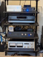
It's integrated into my system and singing. Replaced a Korg Nutube preamp with separate switch box.
Initial impressions are that it is more detailed and in control of the sound, especially the bass (Rhythmic subs with 1.5QR). Very pleased. Thanks ZM.
Initial impressions are that it is more detailed and in control of the sound, especially the bass (Rhythmic subs with 1.5QR). Very pleased. Thanks ZM.
Attachments
- Home
- Amplifiers
- Pass Labs
- Iron Pre Essentials Kits For The DIYA Store - Register Your Interest