Its a little early for halloween decorations…. But who am I to judge….


I have a question about inputs and outputs. It looks like the boards support multiple inputs and one output. I'd like to configure a build for three in and three out all balanced. Is that possible without using another solution for the switching?
If you'd like all 3 outputs active at the same time, then you don't need anything special. Just wire the three in parallel. My guess (uneducated) is that if Zin of the amplifiers is sufficiently high, then it will be no issue. ZM may have some further insight. I'd wait for him to give it the final approval. Depending on your preference, you could also use a simple XLR splitter.
For inputs - Set up 3 balanced inputs. No need for the relays etc. for the other two inputs you will not be using. Only one input would be active at a time. The inputs are switched.
For inputs - Set up 3 balanced inputs. No need for the relays etc. for the other two inputs you will not be using. Only one input would be active at a time. The inputs are switched.
Last edited by a moderator:
inputs - selector is absolutely necessary; think impedances
even if I don't believe that sbelyo meant actually using inputs in PA fashion, actually mixing/paralleling them
outputs - Rout of Iron Pre is practically Rout of buffer multiplied with impedance ratio (square of autoformer voltage ratio)
in case of balanced, voltage gain is 6db, 2V/V, so impedance ratio is 4
A. Rout of complementary Toshiba buffer is ((1/xconductance + source resistance) of N channel JFet) in parallel with ((1/xconductance + source resistance) of P channel JFet)
B. Rout of non-complementary Toshiba buffer is ((1/xconductance of N channel JFet) divided with number of N channel JFets + source resistance
Rough calculus for both cases ( A covering first 2 batches of Iron Pre, B covering all following, with smd JFets):
A. xconductance of 2SK170 and 2SJ74 roughly 20mS, 20R trimpot forming two source resistors in parallel)
so buffer Rout = (1/20mS +10R) // (1/20mS +10R)= 30R
that multiplied with 4 (got from autoformer), Iron Pre is having 120R Rout, per phase
B. xconductance of 2SK2145 is roughly 15mS per JFet, having 2 JFets per tiny case and we are using them as combo, thus 30mS
also, we have 2 pieces of 2SK2145 in parallel, so xconductance sum is 60mS
source trimpot in most cases will end in, say, 15R region
so, 1/60mS + 15R = Rout of buffer = 32R
that multiplied with 4 (got from autoformer), Iron Pre is having 128R Rout, per phase
conclusion - if driving following stages (power amps) in parallel with Iron Pre, no problem if they are of at least moderately high Rin, "moderately" starting from 15K, then up, be it 2 amps, or even 3
edit: parallel amps must be used in "ON" state all the time; note that some amps (depending of input stage topology) when in Off state are actually having much lesser Rin, thus simply eating input signal, not leaving clean one for amp actually working
Last edited:
Thanks for this... I'm not 100%sure of the Rin of the 3 amps. I do know that 2 or them are 2SK170 and 2SJ74 based inputs. The third is a bottlehead S.E.X. 2.1inputs - selector is absolutely necessary; think impedances
even if I don't believe that sbelyo meant actually using inputs in PA fashion, actually mixing/paralleling them
outputs - Rout of Iron Pre is practically Rout of buffer multiplied with impedance ratio (square of autoformer voltage ratio)
in case of balanced, voltage gain is 6db, 2V/V, so impedance ratio is 4
A. Rout of complementary Toshiba buffer is ((1/xconductance + source resistance) of N channel JFet) in parallel with ((1/xconductance + source resistance) of P channel JFet)
B. Rout of non-complementary Toshiba buffer is ((1/xconductance of N channel JFet) divided with number of N channel JFets + source resistance
Rough calculus for both cases ( A covering first 2 batches of Iron Pre, B covering all following, with smd JFets):
A. xconductance of 2SK170 and 2SJ74 roughly 20mS, 20R trimpot forming two source resistors in parallel)
so buffer Rout = (1/20mS +10R) // (1/20mS +10R)= 30R
that multiplied with 4 (got from autoformer), Iron Pre is having 120R Rout, per phase
B. xconductance of 2SK2145 is roughly 15mS per JFet, having 2 JFets per tiny case and we are using them as combo, thus 30mS
also, we have 2 pieces of 2SK2145 in parallel, so xconductance sum is 60mS
source trimpot in most cases will end in, say, 15R region
so, 1/60mS + 15R = Rout of buffer = 32R
that multiplied with 4 (got from autoformer), Iron Pre is having 128R Rout, per phase
conclusion - if driving following stages (power amps) in parallel with Iron Pre, no problem if they are of at least moderately high Rin, "moderately" starting from 15K, then up, be it 2 amps, or even 3
edit: parallel amps must be used in "ON" state all the time; note that some amps (depending of input stage topology) when in Off state are actually having much lesser Rin, thus simply eating input signal, not leaving clean one for amp actually working
I could just put a Goldpoint switch on the output and call it a day but I thought I'd ask what the possible configs could be.
I could just put a Goldpoint
if you're not going to use them all in same time, that would be best
@Zen Mod
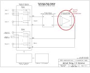
I was planning on using AMB labs LCDuino-1 system to build a preamp. It consists of a display and controller, input/output selector, and a volume attenuator. You can use your own pre amp circuit so I thought this might be worth a try since I already have the kit
LCDuino-1 system
https://www.amb.org/audio/lcduino1/
https://www.amb.org/audio/delta1/
https://www.amb.org/audio/delta2/
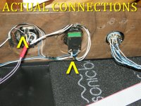
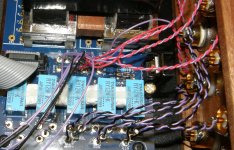
Since it is the Iron Pre that I have built and love, now is a time for me to address one issue. Only when I use the Iron Pre at near or at its highest output, I get a hum but only in the right channel. I suspect a grounding issue, and since it only affects one channel I tend to believe that it may not be an issue concerning transformer placement. Are there other obvious things that might cause this? Yes, the pre is completely built and has been in use for some time. I only noticed this recently when using a phono preamp with it and no, it doesn't matter that I am using a phono pre or other type of input, the hum remains at high levels.
Thanks guys.
Thanks guys.
Attachments

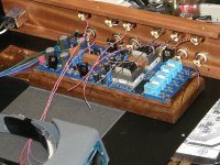
Not my best wiring by a long shot, and incredibly difficult to get a sharp photo since the focus is all over the place. Let me try some more.
Attachments
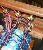

can't really see wheretf is pot situated
besides position of Donut regarding signal iron, that's single remaining critical factor
besides position of Donut regarding signal iron, that's single remaining critical factor
The more that I look at this wiring, whether good or bad, the more that I just want to redo it all. The way that I went about mounting these pots will make it difficult though. This is a TKD pot, and so I will order a new one anyway, and go from there. The balance control looks equally bad. Truth be told, for whatever reason this was one of the most difficult wiring jobs that I ever did due to poor planning, so take note. At this point it will be one thing at a time and done correctly.
Attachments
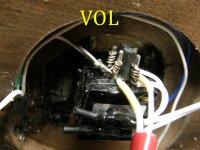
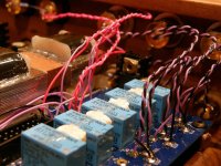
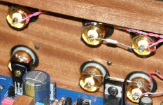
now's just one picture missing , so I can see it all, how it's arranged
why balance?
make your efforts to move pot all the way to pcb, extending shaft is easy, once when you try it
as connecting element, you can use even 5mm inner Dia hose, for car or mcycle gas lines
work as charm, allows you to even be clumsy with centering of things
as shaft, even threaded bar can be used, easy to get in nearest tech. store
- Home
- Amplifiers
- Pass Labs
- Iron Pre Essentials Kits For The DIYA Store - Register Your Interest