
The switch passed the buzz test following ZM's above instructions, and the cables passed the test, too (relays clicked just fine when shorting female ends). I'm stumped. Granted, I've been stumped the whole time, haha! @aljordan is kindly sending me another twister board, so I'll try swapping that in when it arrives.
But in the meantime, I will happily switch the inputs manually! I just put on a record and... holy moly it sounds incredible! Thank you so much, ZM, for this beautiful sounding preamp, for your and IAIMH's indefatigable troubleshooting help, 6L6 for the build guide, and everyone else chiming in along the way. All my previous builds went relatively smoothly, so I guess I was due for a stumper! 🙂
But in the meantime, I will happily switch the inputs manually! I just put on a record and... holy moly it sounds incredible! Thank you so much, ZM, for this beautiful sounding preamp, for your and IAIMH's indefatigable troubleshooting help, 6L6 for the build guide, and everyone else chiming in along the way. All my previous builds went relatively smoothly, so I guess I was due for a stumper! 🙂
^ Fantastic... 🙂
Well... it's 99.9% something with the switch itself. There's not much that can go wrong with the twister board.
Again... only if you're willing...
First (re)confirm that you have 5 clicks (6 positions) set on your switch. You may have confirmed, and I missed it.
Plug in the cables on both ends.
Do same exercise with shorting + to 1-5 using the pads on twister board. 99% should get full clicks... which leads to it 100% being switch.
Remove cables.

DMM set to continuity -
Put one probe on A side center pad. Turn switch full CCW.
Put other probe to A1. Does it beep? If not, which one pad makes it beep?
Turn one click CW - Move probe to A2. Does it beep? If not, which makes it beep?
One more click A3... then one more A4, then one more A5, then one more... A6.
Same for C side.
Well... it's 99.9% something with the switch itself. There's not much that can go wrong with the twister board.
Again... only if you're willing...
First (re)confirm that you have 5 clicks (6 positions) set on your switch. You may have confirmed, and I missed it.
Plug in the cables on both ends.
Do same exercise with shorting + to 1-5 using the pads on twister board. 99% should get full clicks... which leads to it 100% being switch.
Remove cables.
DMM set to continuity -
Put one probe on A side center pad. Turn switch full CCW.
Put other probe to A1. Does it beep? If not, which one pad makes it beep?
Turn one click CW - Move probe to A2. Does it beep? If not, which makes it beep?
One more click A3... then one more A4, then one more A5, then one more... A6.
Same for C side.
The switch checks out on the continuity test. It beeps appropriately for each of the click positions testing from the pads. (And yes, confirming that I did get the switch properly set up for 6 positions).
But the relays don't click when shorting from the twister board pads.
But the relays don't click when shorting from the twister board pads.
Then... yep it's odd... but then the cable isn't making continuity through the pins on the header through to the PCB.
Never woulda thunk it... but we had to check it to be thorough. There's the 1%
Those headers are a pain to de-solder / re-solder. Since you have a new twister on the way...
Enjoy the tunes and wait...
🙂
99% should get full clicks...
Never woulda thunk it... but we had to check it to be thorough. There's the 1%
Those headers are a pain to de-solder / re-solder. Since you have a new twister on the way...
Enjoy the tunes and wait...
🙂
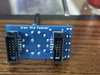
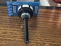
Compared to the working ones I've soldered, you have your rotary switch upside down. Don't know if it makes a difference.
Only if you're using the little 'nubbin' for alignment on a chassis with a pre-drilled hole... and you accidentally install it the other way... and there are LED holes in the chassis... so you can't really just flip the board over.Compared to the working ones I've soldered, you have your rotary switch upside down. Don't know if it makes a difference.
Ask me how I know...


Nope... still an awesome offer though.Oh, mine is a v3 board. I guess it won't work with his then?
@spryor - I happen to have this one in front of me... I'll send it out tomorrow if blue LEDs won't kill ya (or you can swap them).
Edited to add - I truly don't remember if I put this in a unit... or if it was tested in situ, but... it should be fine.
Attachments
Thanks for kind offer, Alan, and Patrick for checking on the board version and sending a twister board and switch my way. I said it before a few pages back, but it bears repeating: you all are the best!
^ Any time. I admit to still being puzzled by this one... 
I thought I'd ruled it out when I asked if all the LEDs then lit and in the proper sequence. That shows definitively proper contact from main board through cable to header to twister PCB through circuit from "+" to "-" and back to main board ...
I'm out of ideas except to try a new one. Maybe someone more creative/smarter can think of something.
If it works... lovely. If it behaves the same way...
I thought I'd ruled it out when I asked if all the LEDs then lit and in the proper sequence. That shows definitively proper contact from main board through cable to header to twister PCB through circuit from "+" to "-" and back to main board ...
I'm out of ideas except to try a new one.
Maybe someone more creative/smarter can think of something.If it works... lovely. If it behaves the same way...
I'm out of ideas
me too
everything checking of, but no go
I'm doubting first in some of checking, but what do I know....

I'm doubting it, too, ZM! Even with your and Patrick's detailed guidance, it's entirely possible that I'm checking something incorrectly. If the new switch doesn't solve the issue, then we can confirm that at least one issue is my faulty checking! 😉I'm doubting first in some of checking, but what do I know...
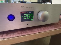
Back in Nov ‘23 I snagged one of the last balanced essentials kit. And, after @Skylar88’s enthusiastic endorsement of the ESP32, decided I’d use the IP as a platform to learn this new-to-me uC.
Here’s the result, a tape monitor, AV bypass, two balanced inputs and Muses 72323 volume control . Thanks to Frank Wilker for the great idea of mounting the Muses chip millimeters from the IP connection points (although I baulked at using solder as the sole support and used right-angle pins), thanks to @jpk73 for the debounce library and the refining of the Muses library. Thanks again to @Skylar88 for the ESP32 tips n’ tricks and, in case he’s beginning to feel left out - big thanks to ZM for the great-sounding Iron Pre! Lots of porn…


Here’s the result, a tape monitor, AV bypass, two balanced inputs and Muses 72323 volume control . Thanks to Frank Wilker for the great idea of mounting the Muses chip millimeters from the IP connection points (although I baulked at using solder as the sole support and used right-angle pins), thanks to @jpk73 for the debounce library and the refining of the Muses library. Thanks again to @Skylar88 for the ESP32 tips n’ tricks and, in case he’s beginning to feel left out - big thanks to ZM for the great-sounding Iron Pre! Lots of porn…
Attachments


- Home
- Amplifiers
- Pass Labs
- Iron Pre Essentials Kits For The DIYA Store - Register Your Interest