I got a really good question from a build I did a while ago... the person asked how I wired up my "Mute" LED. I used blue for the inputs and red for the mute.
I don't have that build any longer, and I'm going by memory, but I'm pretty sure this is how it can be / was done.
If you don't need a different value of the current limiting resistor...

If you use a different color or just want to use a different value...

Note... this shows the original twister boards. Those with V.3 twister boards... I hope you can figure it out. 🙂
Heck, I hope I got it right. I'm not too swift with these things. I just poke around with a DMM and listen for the beeps.
I don't have that build any longer, and I'm going by memory, but I'm pretty sure this is how it can be / was done.
If you don't need a different value of the current limiting resistor...
If you use a different color or just want to use a different value...
Note... this shows the original twister boards. Those with V.3 twister boards... I hope you can figure it out. 🙂
Heck, I hope I got it right. I'm not too swift with these things. I just poke around with a DMM and listen for the beeps.

It sounds like I have no gain whatsoever! I have the earliest version of the boards. All voltages check out fine but I seem to have no gain. If I put my ear to the speaker I can hear the source playing and the volume control will work as expected but the sound cannot be heard at all from more then a few inches away. Surely I've made some dumb mistake. I initially thought I must have wired the volume pot incorrectly at it's board so I went ahead and soldered directly to the pins of the pot to rule that out. No difference. Can anyone point me where to start?


I'd trace a signal through the path.
Get a signal at one of the inputs. 0.5 to 1Vrms at 60Hz to 1kHz. No need for accuracy. You'll be checking with a DMM. Just pick a frequency and voltage. All you're checking is to see where the signal gets lost on its way in/out. Use a phone or whatever. No need to be picky.
Measure with DMM referenced to GND set to ACV.
Edited for (hopefully) a bit more clarity. 🙂
Get a signal at one of the inputs. 0.5 to 1Vrms at 60Hz to 1kHz. No need for accuracy. You'll be checking with a DMM. Just pick a frequency and voltage. All you're checking is to see where the signal gets lost on its way in/out. Use a phone or whatever. No need to be picky.
Measure with DMM referenced to GND set to ACV.
- Check at the input selected
- Check at pot pads on Iron Pre board
- Check at pot pads on pot board
- If signal looks good at pot pads on board, then move the volume up and down. Make sure pot works properly. Turn volume all the way up.
- Check signal at gain jumper pins
- Check signal at output
Edited for (hopefully) a bit more clarity. 🙂
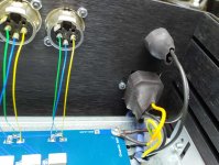
as IAIMH wrote
that open-fashion of mains switch is lousiest possible on earth
buy big dia heatshrink or whatever similar, isolate that, and also some plastic foil on terminal block
there is no reason that we have open=to=touch mains contacts in our DIY builds
that open-fashion of mains switch is lousiest possible on earth
buy big dia heatshrink or whatever similar, isolate that, and also some plastic foil on terminal block
there is no reason that we have open=to=touch mains contacts in our DIY builds
I'm a firm believer in Occam's Razor and when nothing worked I assumed it was my mistake since my two hands built this thing. I was perplexed with how whatever mistake I had made would affect each channel equally. After troubleshooting from the signal inputs I realized the RCA cables I hooked up for test purposes weren't compatible with the jacks I installed as the center pins weren't making connection. Threw them away, used a different pair and now all works as it should. Sounds beautiful!!It sounds like I have no gain whatsoever! ... Can anyone point me where to start?


Yes; it drives one crazy! I've built far more complex equipment that worked correctly right away and this thread is not full of people having issues, so I kept asking myself "what bonehead mistake did you make???" Always go back to the basics. Did you plug it in? Did you turn it on? Do these godforsaken cheapie RCA cables work? 😛OMG, don't you just that kind of crap? I would have assumed the same thing. I am glad that you figured it out before everything got all torn apart looking for the little demon.
I used to rebuild Carver C-9 units that I thought that the addition of an on/off switch would be a good idea. I quickly changed my mind when one customer after another claimed that they didn't work. "Did you turn it on?" I would ask. Always, the same silence from the other end. "Did you read the ad description?" and on it went. Easier just to leave things alone in that case.
This unit fortunately has none of that going on at least in my experience. I am building another one, maybe just for practice. Parts are on the way.
This unit fortunately has none of that going on at least in my experience. I am building another one, maybe just for practice. Parts are on the way.
It's alive! Sounds and functions great. Voltage and offset are rock steady. And yes, I know the terminal block should be shielded. Is there a reason for this other than EMI? There is zero hum as-is.

Is there a reason for this other than EMI?
conscience, proper praxis, prevention, principle
example of approach attached
I'm pretty much leaving semi-approachable mains contacts only if (soft start) NTCs involved - can't isolate because they need air
Attachments
@birdbox - if you have a vice and a drill (or better, a drill press), you can make your own by making a right-angle bend, drilling screw holes in the foot, then measuring the locations for the pot bushing/shaft and drilling with a step drill. It might be easier for you to 3d print - for me, the metalwork is easy and I have no way to 3d print.
50 VA each
20VA per channel is more than enough
bigger just means bigger risk of interference
- Home
- Amplifiers
- Pass Labs
- Iron Pre Essentials Kits For The DIYA Store - Register Your Interest