I am just observing from the sidelines, and hope to learn something myself. I would be curious to see the bottom side of the board. From this side, it almost looks like a center pin was not soldered on Q2. I am sure that it is, but the solder did not come through the hole. I guess that it would only account for the V- power rail anyway.

Have you checked for excessive heat in any components, indicating excessive current draw? Is this plugged into a current meter, and if so, what is the AC draw?
I meant - all parts, check
have you some DC after bridge diodes?
at least that is easy to measure, ref to gnd
have you some DC after bridge diodes?
at least that is easy to measure, ref to gnd

One more slowly coming together, awaiting goodies from Italy.
It’s going to be weird having a preamp in a factory case…not made of things I found in the garage 🙂

It’s going to be weird having a preamp in a factory case…not made of things I found in the garage 🙂
I am still laughing. I just came back from my shop (the garage) with a smallish black walnut board, that was barely the right size for my build. And it so true. You see a piece here or there and kind of wonder to yourself whether it should be saved for that special thing or not.
Attachments

Thats awesome 🙂
After finishing the Iron Pre I plan to build another preamp case, and one for an amp, to use up spare parts from old projects.
Too many homeless built out boards also laying around to not at least have somewhere to put them, if wanted.
After finishing the Iron Pre I plan to build another preamp case, and one for an amp, to use up spare parts from old projects.
Too many homeless built out boards also laying around to not at least have somewhere to put them, if wanted.
Do I need to keep trying to separate this one?
of course
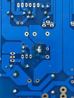
school example of cold solder joint
crank the iron, use bigger tip, use helper flux if you have it
No excessive heat.
25vdc on diodes
if nothing on rails (output/test pads) ....... there is simple strategy for you - remove all transistors (bjts and mosfets), clean pcb pads, check every resistor and diode on pcb(easier when transistors are out), check each transistor, solder back one by one, replace if needed
then post proper pictures here, without powering up, and then power it up only when you get green light to do the same
having no mileage is one thing, having unshaved pins touching the case is ....... inexcusable example of rushing things

No heat at all on the MOSFETs.Reflowed everything. 3vdc is all it can muster. I'm not frustrated I'll keep using the passive until I get this taken apart
A good checkpoint I used was to measure voltage over the R3 \\ R4 and over R5 \\ R6 to check if there is about 0.6 VDC.
Also good to be 100% sure it is a BC546 at positive rail together with BD139 and negative rail has BC556 together with BD140.
I think until this part is in place no need to look further up in the circuit (unless there is a short or course).
But if you only have 3 VDC after the diode bridge this much be fixed first.
If diodes are reversed I guess someone would have noticed it from the pictures? ......maybe recheck to be 100% sure?
If AC is correct and DC after diodes are only 3 VDC then the diodes should be investigated (and also checked for cold solder joints)?
The 3 solder joints here at top looks bad (cold) same at the bottom. Holes should be filled out with solder.
Hopefully it looks better after reflow?

Hopefully it looks better after reflow?
If AC is correct and DC after diodes are
he said having 20Vsomething after diodes, while 3Vsomething at rails
obviously there are several possible culprits, but fact of both rails ooked up means there are several errors in assembly
I know it's bother, but pulling actives and working (again) slowly and checking every part is actually fastest way of troubleshooting for someone who's not doing that as day job
heck, puzzle approach works and it is fully justified, but not without utmost care in each step; means - each part must be taken care of with same importance, same as each and every solder joint
- Home
- Amplifiers
- Pass Labs
- Iron Pre Essentials Kits For The DIYA Store - Register Your Interest