Thanks sir
My rail is 35vdc drivers are bd139.140 input pair bc549 offset 3mv gate volt3.5v sorry for my poor english
Thanking you
My rail is 35vdc drivers are bd139.140 input pair bc549 offset 3mv gate volt3.5v sorry for my poor english
Thanking you
Last edited:
Nice job sownel. 🙂
What speakers are you using?
Thank you sir
My speaker jbl 10"woofer and old bolton 8"tower box nice sounding
Thanks sir
My rail is 35vdc drivers are bd139.140 input pair bc549 offset 3v gate volt3.5v sorry for my poor english
Thanking you
3v offset is quite high, it should read in mv range.
Check your input pairing, and the offset trimpot adjustment at the LTP current source, adjust to get a reading in mv range.
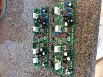
Here is my progress:
I'm still waiting for the magnetic wire to arrive.
I need to know a few things:
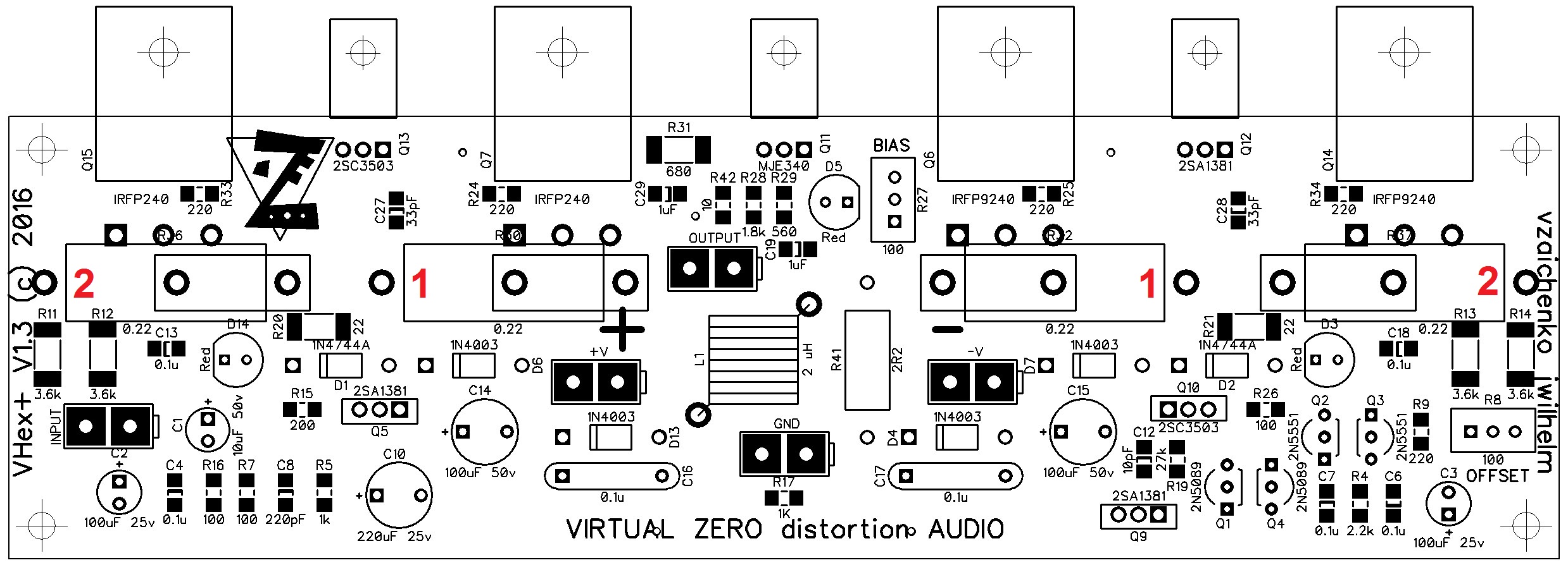
What is the bias value?
Where do I measure the bias?
Bias rises clockwise or anti-clockise at the trimmer?
Nice work!
For bias adjustment, see post 270. Put DMM test leads on points 1-1 and set voltage across 0.22R+0.22R for 80mA (about 35mV). Double check across points (2-2) and should be double at about 70mV.
Please use two 10R, 10W safety resistors (one each) between power supply rails and amp and monitor voltage across that during initial turn on to make sure nothing is terribly wrong. It will limit current so you don't fry the outputs in an instant. I think CCW increaases bias if I remember right - not critical as you will see effect as you turn screw.
http://www.diyaudio.com/forums/soli...-amplifier-simulated-tina-27.html#post4726968
Last edited:
Bias should be around 80mA. Measure the voltage drop across a pair of emitter resistors to figure out the bias. If you are using 0.22R emitter resistors, you should read 36mV.
Set the bias pot to it's highest resistance. You have them installed in opposite directions, so setting will be in opposite directions to each other. Set the offset pot to around the center
Set the bias pot to it's highest resistance. You have them installed in opposite directions, so setting will be in opposite directions to each other. Set the offset pot to around the center
I used some magnet wire I found in my parts bin and tested the amp. Unfortunately I have smoke in the two 10R 1W resistors at the rails. 🙁 What do I do now? While on bias starts at a few mV and then rises to about 10mV. After that I unplug the amp.
First, double check all your transistor orientation and location. With power disconnected, measure the resistance of each power rail to ground, and each power rail to your heat sinks.
It looks like you may have Q9 & Q10 installed backwards. The square pads are transistor base, which is pin 3 on a TO-126.
Use a bulb limiter for initial testing to stop smoking parts too.
It looks like you may have Q9 & Q10 installed backwards. The square pads are transistor base, which is pin 3 on a TO-126.
Use a bulb limiter for initial testing to stop smoking parts too.
Last edited:
Nice work!
For bias adjustment, see post 270. Put DMM test leads on points 1-1 and set voltage across 0.22R+0.22R for 80mA (about 35mV). Double check across points (2-2) and should be double at about 70mV.
http://www.diyaudio.com/forums/soli...-amplifier-simulated-tina-27.html#post4726968
1-1 and 2-2 should actually be the same voltage if the output pairs are matching.
Nice work!
For bias adjustment, see post 270. Put DMM test leads on points 1-1 and set voltage across 0.22R+0.22R for 80mA (about 35mV). Double check across points (2-2) and should be double at about 70mV.
Please use two 10R, 10W safety resistors (one each) between power supply rails and amp and monitor voltage across that during initial turn on to make sure nothing is terribly wrong. It will limit current so you don't fry the outputs in an instant. I think CCW increaases bias if I remember right - not critical as you will see effect as you turn screw.
http://www.diyaudio.com/forums/soli...-amplifier-simulated-tina-27.html#post4726968
Everything's right, but the voltage between 1-1 and 2-2 should be the same (35-36mV) 😉
Ah Jeff, noticed your previous post too late 🙂
Last edited:
I made some progress. The issue is the bias. I was starting the amp with a bias value to high. But there's still a problem: the lower bias value I get is about 89mV (trimmer all the way conterclockwise). If I turn the trimmer clockwise the bias increases to a lot.
One of my amps initially had a very high railed output and finally traced it to a cold solder joint at R20 (22R 1W). When everything is soldered and placed right, this amp fires up with stable bias and offset. Took a day an removing a bunch of transistors to track that down though. So look for suspect SMT solder pads.
@vzaichenko and jwilhelm: sorry I messed up that 2-2 probe point for the bias - so thanks for catching that. I remember there was a point where the voltage was doubled, imagining it?
@vzaichenko and jwilhelm: sorry I messed up that 2-2 probe point for the bias - so thanks for catching that. I remember there was a point where the voltage was doubled, imagining it?
One of my amps initially had a very high railed output and finally traced it to a cold solder joint at R20 (22R 1W). When everything is soldered and placed right, this amp fires up with stable bias and offset. Took a day an removing a bunch of transistors to track that down though. So look for suspect SMT solder pads.
@vzaichenko and jwilhelm: sorry I messed up that 2-2 probe point for the bias - so thanks for catching that. I remember there was a point where the voltage was doubled, imagining it?
Many people recommend measuring bias across a single emitter/source resistor, which would be 17-18mV. Valery's recommendation is across two emitter resistors, which doubles the value.
Curious question: The inductor used in the Thiele network, is that a commercially available part? If so, who makes it?
Thanks,
Tom
Thanks,
Tom
Curious question: The inductor used in the Thiele network, is that a commercially available part? If so, who makes it?
Thanks,
Tom
I've never seen them available anywhere. We usually just hand wind them. They're really simple to do with a bit of practice.
- Home
- Amplifiers
- Solid State
- IRFP240/9240 Amplifier (simulated on TINA)