
@wkloppen Thanks for sharing your .DXO file. However, I wasn't able to read it because of the localization of the numbers: ',' used to represent '.'. I got a divide by zero error, or suchlike, when I tried to read in your file. Anyway, I just recreated your circuit diagram and its component values, and the filter function frequency responses results matched yours very well. So that side of things is working here at my end.
I do have a question. I noticed that the labels of the capacitor and resistor components in your spreadsheet component list do not seem to match up with the components in the XSIM circuit diagram. Is there an updated spreadsheet available that better corresponds to the circuit used in XSIM?
I do have a question. I noticed that the labels of the capacitor and resistor components in your spreadsheet component list do not seem to match up with the components in the XSIM circuit diagram. Is there an updated spreadsheet available that better corresponds to the circuit used in XSIM?
Last edited:
Hi witald...thats correct. The labels in the spreadsheet are the actual labels of the PCB. The labels in XSIm are automatically generate while creatting the schematic and hence do not matchup with the excel🙂....i haven't had a closer look at the dxo file. I probably will be able to edit the text file and match them up.labels of the capacitor and resistor components in your spreadsheet
Note: I found out the file I posted was somehow corrupted. Maybe caused by the fact I editted the file on 2 different laptops while saving the dxo on google drive. need to draw it up myself again as well but thats done in 15 minutes.
sorry for the confusion. I will post the repaired file. Btw...you can edit the notepad file and change the labels.
sorry for the confusion. I will post the repaired file. Btw...you can edit the notepad file and change the labels.
Those are some big layout changes! Do you happen to have the original circuit diagram published by KEF by any chance?
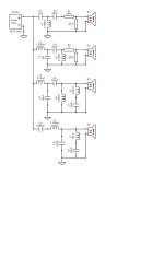
unfortunatly not.....the schematic was reverse engineered by someone on this forum a couple years back. I've checked the schematic with the pcb traces and components when I refurbished the speakers and replaced the caps. Provided I did not make a mistake...this should it.🙂original circuit diagram
I decided to give it go and start to rework the oem XO's of my Kef Reference Model Three's built in 1996. i've read a lot including the mathemematics on ESP pages of Rod Elliot. https://sound-au.com/index.html The first challenge is flattening the impedance of each driver. I will be using the DATS V3 as main tool in order to aquire the T/S parameters. My question is this. I first need the free air impedance curve. Is it enough to just loosen each driver making sure there is free air behind them or do I need to mount them on/in a seperate open board or something like that. After that i will use the added mass method.
In the original scheme I see inductors with capacitors in series parallel of the lower mid and sub drivers which would be indication of some resonating compensation I guess. It'll probably work a bit as zobelling circuit to correct the rising impedance with frequency....not sure though
The second challenge might be even more difficult and that is determining the xo frequencies as I need 3 of of them
All in all some challenges I'm looking forward to but I'm in no rush at all. I like to learn and understand whats going on and I'm not afraid of the math involved.
I will post the dat once i've got them but I will need help determing the xo frequencies........
reg
willem
You don't need the T/S parameters to work a crossover. You don't need the free air impedance. You only need to measure the impedances of the drivers in the box.to aquire the T/S parameters. My question is this. I first need the free air impedance curve. Is it enough to just loosen each driver
If you can measure the filter responses (at the driver terminals) for the original crossover then you can use those as comparison curves when you simulate.determining the xo frequencies
Ah..that makes it a little bit easier🙂....You only need to measure the impedances of the drivers in the box.
That's no problem I guess,... using the oscilliooscoop function in teh DATS. Never used it before though but we'll see what's coming out of it.measure the filter responses (at the driver terminals) for the original crossover
Ok...but I can't use the dats v3 generating a signal and measuring the xo FR at the same time....can I....
I would still be needing an audio interface like Focusrite Scarlett 2i2 or MOTU M2 or something.
I see your point.
If a computer has sound in/out built in or has a card, there's no need for another interface.
As for the other, RTA software can act as a generator on it's own.
If a computer has sound in/out built in or has a card, there's no need for another interface.
As for the other, RTA software can act as a generator on it's own.
I'have 2 windows 11 laptops . Both with built in soundcards. Maybe a stupid question but how do I connect the laptop to the XO then? I can use the dats for either signal generation (connected to the input of the XO) or oscillioscope mode (connected to the outputs of each driver one by one. But not at the same time.sound in/out built in
Clearly you need to choose something to use as a target and that depends on your plan, your choice. Using a microphone might be less consistent whereas electrical measurements will be more precise, but you might need extra steps on the simulator to compare filter responses.
If you choose to go that way, apply the noise or sweep signal to the speaker in the usual way and read the terminals, one shot per driver.
Make sure you take care of levels (you might use an attenuator) and AC coupling (if necessary) so as not to damage the sound card.
If you choose to go that way, apply the noise or sweep signal to the speaker in the usual way and read the terminals, one shot per driver.
Make sure you take care of levels (you might use an attenuator) and AC coupling (if necessary) so as not to damage the sound card.
Was thinking about a Focusrite Scarlett 2i2 4th Gen Audio Interface in combination with rew to measure the FR. Will this combination be suffient enough to determine the values for all the R, the L's and the C's?
reg
w.
reg
w.
Yes it can, but you need to be consistent. Take each driver's acoustic measurements one after the other for with and without crossover, and don't move anything.
Understood....when I measure a driver at the driver terminals WITH cross-over.......do you have to disconnect the other drivers from the cross-over? From an electrical point of view the voltages to each driver is exactly the same but for the amps hence the power obviously aren't. I would assume that it doesn't make any difference for the measurements....not sure though...🙂don't move anything.
No.when I measure a driver at the driver terminals WITH cross-over.......do you have to disconnect the other drivers from the cross-over?
Leave the input the same when you measure each.From an electrical point of view the voltages to each driver is exactly the same but for the amps hence the power obviously aren't. I would assume that it doesn't make any difference for the measurements...
When simulating, you'll have to find the right level somehow. When you change it, change each of the driver target curves together.
- Home
- Loudspeakers
- Multi-Way
- Introduction to designing crossovers without measurement