Thank you kindly again Allen, will purchase some tools to learn how to measure as I move along. Re RLC does it coincide with the choosen Xo frequency or its independant & base solely on the driver parameters. Also how does it react with the XO network ?
Thank you kindly
Thank you kindly
If you use RLC to flatten the impedance peak, then this is independent of the crossover. If you do it right, then you do it once, you can change the crossover and pay no attention to it. Because it makes the impedance look like a resistor, it does not react with the crossover.
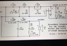
Yes it is; C3/R1 act like a treble tilt which is useful for drivers having a downward frequency slope after 15 kHz
R2 burns some power, being 10 Ω ! It tames the impedance peak of the tw, so the CLC net works on a more linear module.
Thank you again Pico. I tried with XO calculator to check out the frequency but some how I can’t get the C values correct until it get’s to around 2500hz which is unlikely for this design. Where did I go wrong ?
You didn't go wrong. Third order filters are not obvious. Resonance equations may not help.
But this is a waveguide design with a 12" woofer and I guess the crossover frequency is 1k5Hz.
But this is a waveguide design with a 12" woofer and I guess the crossover frequency is 1k5Hz.
Hi Allen thank you again. Seldom see the use of 3rd order XO.
I guess the best way for me know is to build the XO & get some simple equipment & software to measure & learn frm there.
I guess the best way for me know is to build the XO & get some simple equipment & software to measure & learn frm there.
If you design the crossover well, it makes only a small difference between second order, third and fourth, and then only when there is a reason. For example, the order must be big enough to cut the woofer breakup and let the tweeter play loud enough.
Understand Allen thank you again & also to Pico for the tutorial.
Will learn as much as I can.
Take care & Cheers
Will learn as much as I can.
Take care & Cheers
Hi Allen. When I choose a woofer which is more than 6dB below my tweeters efficiency, how
do I calculate this. In your tutorial it goes up to a difference of 6dB.
For instance when the difference is 8dB do I multiply the tweeter's impedance value by
1.4 ? Or do I have to choose different drivers.
do I calculate this. In your tutorial it goes up to a difference of 6dB.
For instance when the difference is 8dB do I multiply the tweeter's impedance value by
1.4 ? Or do I have to choose different drivers.
There is no problem with 8dB. Ideally you could use an L-pad. This is one series resistor and one in parallel. Since these work in a reasonably predictable way, it should be OK to use an online L-pad calculator.
Thanks Allen.
One question about an L-pad. Do I skip the the 10 or 20 ohm resistor from your tutorial and
just use the L-pad.?
The tweeter I want to use is a 6 ohm tweeter and with a 10 ohm resistor it will give me
3.75 ohm which I also use in calculating the second order crossover on the tweeter.
Now are these L-pad calculators designed to keep the tweeter at 6 ohm, or will it change the
tweeters impedance?
The idea with an L-pad would be to keep it at 6 ohms. Specifying this is part of the design procedure. It is also possible to take the impedance to another value but keeping it at 6 will be more likely to work as expected.
- Home
- Loudspeakers
- Multi-Way
- Introduction to designing crossovers without measurement