Guys, guys 🙂.. Thanks so much for the input, I know there are many things to do to improve this and eventually never ending. I changed the 4 tweeters with better ones, only 2 this time, no extra charge. he new sensitivity for the tweeters is 93Db. I will recalculate the values.. but is the logic I adopted good??
Ok, ok.. you're off course rightwith the Amp. It's Christmas, I'll stretch the budget with Santa's help and I'll go for the plate amps. 2 options here:
- Dayton Audio SPA500 500W Subwoofer Plate Amplifier
- Dayton Audio SPA1000 1000W Subwoofer Plate Amplifier
I'll take probable the cheaper one 500W (what do you think?), can't see other difference than the power.. but 500 is plenty. One per each speaker for subwoofer and the normal amp for the other drivers. # amps in total.. uau, you pushed me to a demonic crazy power 🙂) I like it!
But I still need to build a 3 way crossover for the rest of the speakers.
I was thinking at a TLine type of box for the subwoofer but what about the Mid Low, sealed box will do?
Revised system
Speakers:

Flattening impedance according with AllenB lessons:

Bringing everything to 93Db Sensitivity:


And finally the crossover for the MedL, MedH and Tweeter:

As for the lower frequencies I just both 2 of those, one per each box:

They have an lowpass filter and will amplify the 4th speaker in the box which is the subwoofer
May I have your bless for this? Please?? 🙂)
Speakers:
Flattening impedance according with AllenB lessons:
Bringing everything to 93Db Sensitivity:
And finally the crossover for the MedL, MedH and Tweeter:
As for the lower frequencies I just both 2 of those, one per each box:
They have an lowpass filter and will amplify the 4th speaker in the box which is the subwoofer
May I have your bless for this? Please?? 🙂)
You have completely changed the proposal.
The tweeter needs 4.2dB more power than the woofer, whereas before the tweeter needed 8.8dB less power than the woofer.
The tweeter needs 4.2dB more power than the woofer, whereas before the tweeter needed 8.8dB less power than the woofer.
More or less
I let alone the Subwoofer which will be on a separate circuit with its own Amp.
So instead of the four "Tw, MidHigh, MidLow, Woofer", I have now only the first three. I might have changed the names of the drivers because now it makes more sense this "arrangement": "Tweeter, Mid, Woofer, Subwoofer".
So the subwoofer is separate with an active filter as lowpass. The rest of the drivers are in a 3 way crossover system. Logical I can see that as a 2 separate systems but physical they live under the same house.. the box. Which will be BIG :-0
Inductor Questions
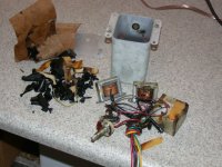
I've gone through several iterations of upgrading the 2-way crossovers in my Vintage Altecs which had a number of compromised design issues including: 1) both inductors next to each other; 2) 50 yo electrolytic capacitors; 3) an inductive wire wound resistor; and 4) old L-Pad.
Originally, I replaced the caps and resistors using a Mundorf Supreme for the HF and electrolytic for the LF, as well as Mills MRA12 resistors (bypassed the L-Pad with a fixed value).
Then, I decided to pull everything out on a board to make adjusting the R easier, to separate the inductors, and to upgrade the LF cap to a Mundorf Supreme now that I had the space. I then went back and replaced the resistors with Duelund using an 18 ohm value on the tweeter (original L-Pad went up to 25 ohms).
The progress to this point was incredible! My neighbor has the same speakers, source, and a similar amp and the differences are well worth it we both agree.
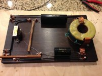
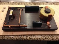
So now on the last revision (V3? V4?) I replaced the LF inductor with a 14 gauge waxed paper in oil 3.5mH inductor, dipped it in bees wax, and mounted it in a 90mm steel capacitor bracket. So far, it's sounded a little bright and bass thin over the past several days. Everytime I've messed with the Mutdorfs they've seemed to go through the same brutal break-in period (this is why I now believe in this effect) and this could very well be the same thing this time but I'm worrying about the effect of this air-core inductor...
The stock 3.5mH VDC value was ~0.5 ohm, and this one is supposed to be .45 Ohm but I didn't actually test it... And also the use of this bracket has me a bit worried. Do foil inductors burn-in? Is it possible that is has a higher DCR and this is shifting more current toward the HF? Could this bracket be reducing the L value on the new inductor adding more upper midrange? Thanks for any ideas or suggestions!
I've gone through several iterations of upgrading the 2-way crossovers in my Vintage Altecs which had a number of compromised design issues including: 1) both inductors next to each other; 2) 50 yo electrolytic capacitors; 3) an inductive wire wound resistor; and 4) old L-Pad.
Originally, I replaced the caps and resistors using a Mundorf Supreme for the HF and electrolytic for the LF, as well as Mills MRA12 resistors (bypassed the L-Pad with a fixed value).
Then, I decided to pull everything out on a board to make adjusting the R easier, to separate the inductors, and to upgrade the LF cap to a Mundorf Supreme now that I had the space. I then went back and replaced the resistors with Duelund using an 18 ohm value on the tweeter (original L-Pad went up to 25 ohms).
The progress to this point was incredible! My neighbor has the same speakers, source, and a similar amp and the differences are well worth it we both agree.
So now on the last revision (V3? V4?) I replaced the LF inductor with a 14 gauge waxed paper in oil 3.5mH inductor, dipped it in bees wax, and mounted it in a 90mm steel capacitor bracket. So far, it's sounded a little bright and bass thin over the past several days. Everytime I've messed with the Mutdorfs they've seemed to go through the same brutal break-in period (this is why I now believe in this effect) and this could very well be the same thing this time but I'm worrying about the effect of this air-core inductor...
The stock 3.5mH VDC value was ~0.5 ohm, and this one is supposed to be .45 Ohm but I didn't actually test it... And also the use of this bracket has me a bit worried. Do foil inductors burn-in? Is it possible that is has a higher DCR and this is shifting more current toward the HF? Could this bracket be reducing the L value on the new inductor adding more upper midrange? Thanks for any ideas or suggestions!
Attachments

Last edited:
You said the coil is mounted in a steel capacitor bracket? That will almost certainly be interfering with the value of the coil. I would get rid of the steel bracket and just mount it to the board with some nylon cable ties and see how it sounds.
Tony.
Tony.
You might also trial a small (1ohm or less) resistance in series with each of the new capacitors.
Hey Allen,
I upped the HF serial R from 12-15 ohms on the L-Pad to 18 ohms when I when with the HF electrolytic cap and liked the HF balance prior to just adding the LF inductor. Would that be the same as compensating for the lower R when I replaced the electrolytic?
This might be a good idea to do with the LF 10uF cap... I have a 2 x 0.22uF Supremes that that I'm not using...maybe that would be okay?
Tony, I might try zip-ties for a wood dowel tomorrow. Thanks!
Nevermind about the 0.22uF cap...wasn't thinking. But yeah maybe I could add a small resistor to the big LF cap.
I'm going off the top of my head here, but I'd assume that increasing the series resistance as you already did, would reduce the damping seen between the larger capacitor and the inductor next to the tweeter, and adding some resistance in series with the capacitor might mitigate this somewhat.
You would also have altered the woofer response a little as this is a series crossover.
Some other thoughts about the new inductor revolve around inter-turn capacitance and the dielectric effect of the beeswax (not that it is a bad thing necessarily and is probably a good thing). The poly capacitor however might interact with it and adding a small series resistance somewhere there might indicate this higher frequency behaviour if it is present, by damping it somewhat.
Last edited:
Yeah, I was really happy with the crossover until I just added the LF inductor - that was the only change with this iteration.
I'll start tomorrow but pulling out the brackets on the inductors and she how she sounds. Then from there I can look at padding the 18ohm resistor a bit more on the horn and/or adding a small R to the large LF cap. The 18 ohm HF serial resistor is just a fixed value in lieu the original HF L-Pad that ranged 0-25 Ohm at full attenuation. Right now it's where the knob would be turned down about 3/4 of the way. With the original crossover (electrolytic) I had the L-Pad at ~12-15 ohms.
I'm still learning a lot with this project but from what I understand ugly original HF parallel inductor is part of the 2nd order HF cross over and the parallel 20 ohm fixed R is some sort of compensation, or to smooth the effective HF impedance seen by the amp? Maybe next step will be to replace that HF ferrite inductor... 😉
About the new LF inductor... it's a 14 gauge waxed paper in oil and was already coated with something probably like paraffin. I'm not worried to much about this just on the outside turn and at the top/bottom of the 40mm foil. If anything I'd hope it would help with microphony and also reduce long-term oxidation. Poor man's Duelund CAST. =)
Thanks for the help mate. I'll keep ya'll updated... ;-)
Just regarding taking low value resistance measurements as with inductors like this. Multimeters can have issues. It can help to twist the lead connections a little and clean the tips, and take a measurement of the leads by shorting them. They'll often have a small resistance themselves. Some have notches on the tips which can be useful for squeezing them onto the inductor lead-outs for good contact. The resistance of your fingers should be negligible here.
In your case it could be worth experimenting with resistance in series with the inductor based on your comments.
I would have assumed the iron would increase the inductance a little. Maybe this could contribute to a lowered tweeter crossover point but with Tony's help you seem to be on top of that 😉
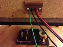
Okay so taking out the steel cap bracket was definitely a good idea... I added a dowel with a brass #10 screw to secure the inductor and used this as an opportunity to make the crossovers external. To do this I had to construct a new connector plate with 4 individual small holes to route the wires into the cabinet. By doing it this way I was able to eliminate the old screw connectors, its solder, and about 2-3 feet of wire to the crossover. Now I can just attach my speaker wire directly to the crossover input. The results at this point are spectacular. I can only guess that the bracket was reducing the inductance on the coil and adding too much upper midrange and it's now sounding really quite nice. 😉
So my next question is it it worth replacing the HF parallel ferrite inductor with another foil air core?
So my next question is it it worth replacing the HF parallel ferrite inductor with another foil air core?
Attachments
Last edited:
 I suspect yes the steel was reducing the inductance of the coil. Steel in the center will increase the inductance, but steel around the outside I think will be similar to mounting on a steel plate, which will reduce the inductance.
 Tony.
I'm almost there, only a decent million problems yet :-(
The subwoofer will be amplified separate (from a plate amp). Will it need an impedance flattening component or the amp will do that.. somehow?
View attachment 3 Way XO and filters.pdf
The 3 way crossover network looks final now, but I still don't like the Mid woofer to be cut so high.. I might change the inductor for the band pass to 0.3mH, will this work well?
Most amps will deal with this but it shouldn't hurt. Some, such as some DIY amps will require it. I've noticed small inprovements with some commercial amps, especially in the lower treble region. Something for a rainy day 😉The subwoofer will be amplified separate (from a plate amp). Will it need an impedance flattening component or the amp will do that.. somehow?
Hi AllenB,
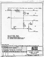
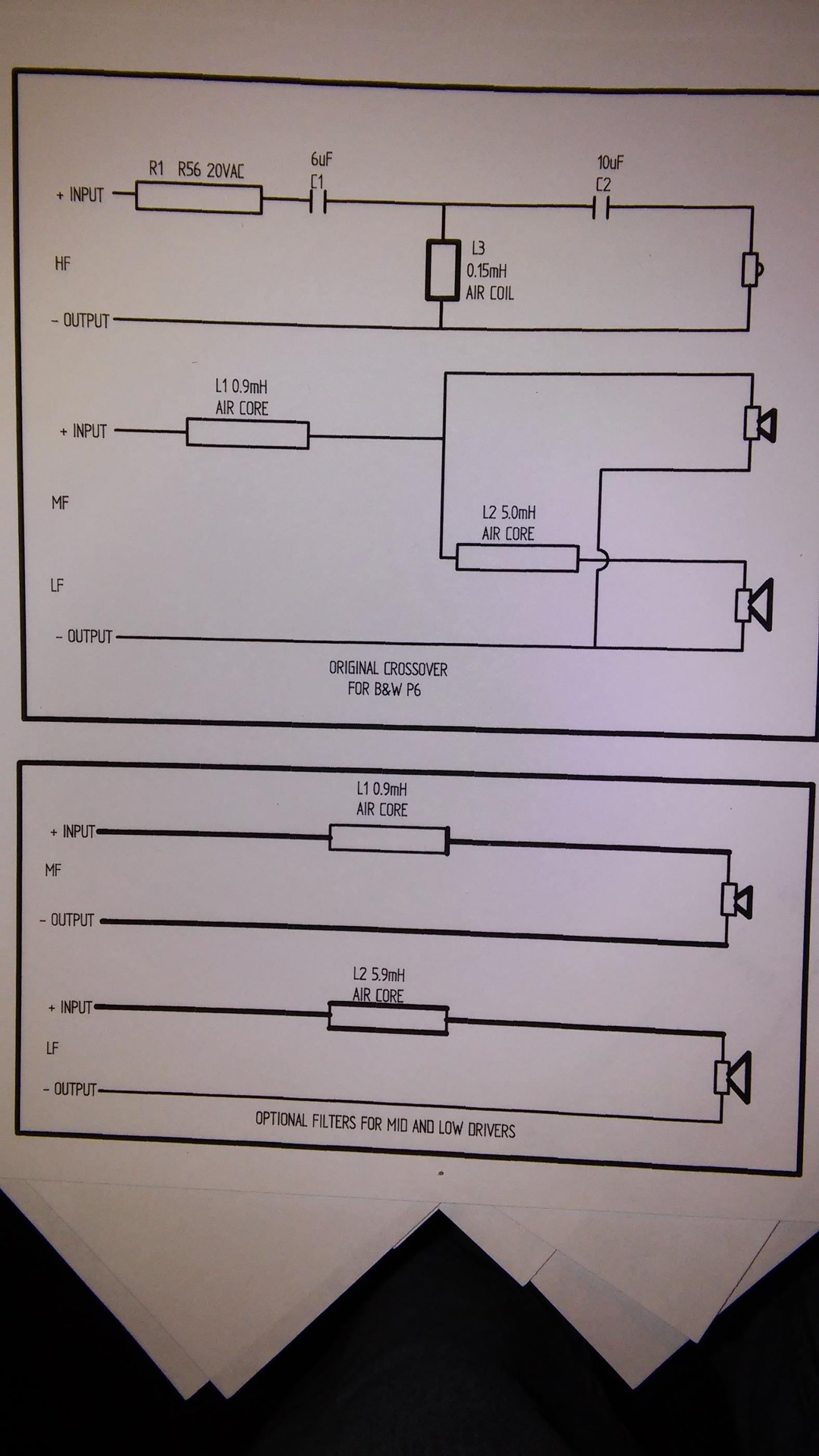
Very impressive and clearly written tutorial. I would really appreciate your input on the attached xover schematics and proposed modifications.
http://www.diyaudio.com/forums/attachments/multi-way/457447d1420464763-xover-mods-0104151459.jpg
Very impressive and clearly written tutorial. I would really appreciate your input on the attached xover schematics and proposed modifications.
http://www.diyaudio.com/forums/attachments/multi-way/457447d1420464763-xover-mods-0104151459.jpg
Last edited:
Hi AllenB,
Very impressive and clearly written tutorial. I would really appreciate your input on the attached xover schematics and proposed modifications. I thought it might be helpful to add the speaker description from B&W site.
3-way 4th order vented box system
1 x 25mm metal dome - high
1 x 165mm Kevlar® - bass/midrange
1 x 165mm Cobex® - bass
40Hz – 20Hz ±2dB on reference axis
90dB spl(2.83V 1m)
8 ohms (minimum 3.5 ohms)
Power Handling
D i m e n s i o n s
F i n i s h
30W – 150W into 8 ohms on
unclipped programme
Height: 1000mm Width: 200mm
Depth: 316mm
http://www.diyaudio.com/forums/attachments/multi-way/457447d1420464763-xover-mods-0104151459.jpg
- Home
- Loudspeakers
- Multi-Way
- Introduction to designing crossovers without measurement