Hi Russ,
Would you be willing to talk a bit about the details of the analog filter circuit? Is it accomplished by just the two 1nF film caps in association with the present resistance of the circuit, or is there more to it? In the first post you mentioned filter corners of 20 K or 30 K, is that correct (seems very low?), and what is the corner frequency with the included parts (1nF)
Thanks for any information which you care to share.
Ah yes - that should actually read 20 or 40Khz
But wow - no - even 20Khz corner is not low - it's near the corner freq of the DAC itself 🙂
You can adjust it by adjusting CF1, CF2A/B where CF1 is double CF2.
CF1 4.7nf and CF2 2.2nf gets a corner just above 20Khz
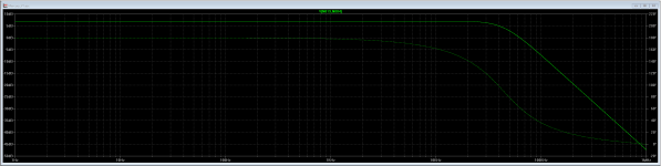
CF1 2.2nf and CF1 1nf get a corner around 40khz
I think you can extrapolate other values on your own - it is important to retain the symmetry to the degree possible with standard values.
I can't think why you would want a corner above 40Khz - but you can do it if you like. 🙂
Here is what the 40khz version ac characteristics are:
Attachments
Russ, that is everything I need to know.
Glad to help - it should be fairly simple to get any corner frequency you want.
If you want to get into the 80-90Khz range I would suggest 1nf and 470pf
Just keep in mind - the further out you go - the less effective the filter becomes at eliminating normal HF DAC artifacts which you really don't want further down the chain.
Cheers!
Russ
I have some Vishay Dale cmf55 249 ohm with 50ppm and 1% tolerance but difference between them is lower than 0.1%. Which resistors did you send us for R1, R2 ? And also did you use thin films for smds?
I have some Vishay Dale cmf55 249 ohm with 50ppm and 1% tolerance but difference between them is lower than 0.1%. Which resistors did you send us for R1, R2 ? And also did you use thin films for smds?
As long as they are closely matched (>=0.1%) they will be fine.
The kit gain resistors are Neohm (http://www.mouser.com/ds/2/418/NG_DS_1773265_A-732392.pdf)
Yes, all SMD resistors are thin film.
Output Z is adjustable (via pads at outputs) we include very small value resistors for safety (I believe we settled on 4.7R) - but you can jumper the pads and make that basically zero ( the closed loop output Z of an OPA1632) if you plan on driving headphone direct then I would add the jumpers (but you actually don't need to) - otherwise - leave it alone.
The same is true for the SE output.
Cheers!
Russ
The same is true for the SE output.
Cheers!
Russ
Thanks Russ, that is kind of what i figured, but without the schema I wanted to be sure. 4.7 will be fine for my uses, low C cabling here.
Excellent - Because of the nature of the filter stage - even with pretty high C it will still be just fine - in fact even with no output resistors (shorted) one should still be just fine. 🙂 The Rs are basically just cheap insurance. 🙂
Russ, when you say that the DC operating point of the ES9038 is dynamic, are there certain situations that cause it to change, such as playback sampling rate or music frequency, or does it vary steadily over time or temperature?
If you don't mind sharing more details of the common mode servo, I was wondering how fast an op amp needs to be to counter the variance and if there are other features of the op amp and/or servo design that are important for this specific task.
Thanks!
If you don't mind sharing more details of the common mode servo, I was wondering how fast an op amp needs to be to counter the variance and if there are other features of the op amp and/or servo design that are important for this specific task.
Thanks!
Last edited:
It comes down to the fact that matching Rs on silicon is never absolutely perfect - and nothing escapes the laws of thermal coefficients 🙂
The idea is not so much for the input side servo to adjust to fast transient conditions - that could actually cause more issues than it solves - those factors are canceled out in other ways. 🙂 The key is that the servo tracks precisely the common mode input current over time.
Thanks Russ -- that's a better way of saying what I was getting at, that the input servo doesn't need to adjust quickly for fast transients. Probably wouldn't be good for anything if the bias was changing abruptly all the time. 🙂
I knew output varied across different chips, but reading the datasheet again I just realized that the impedance can vary across the outputs on an individual chip, which explains the variable DC operating point and makes sense given what you said about mismatches between resistors on silicon.
I knew output varied across different chips, but reading the datasheet again I just realized that the impedance can vary across the outputs on an individual chip, which explains the variable DC operating point and makes sense given what you said about mismatches between resistors on silicon.
That will get you close - nominally it would be 400R - but you will want to adjust up 14% (to allow for DAC output variation) if you don't want to go below 4Vrms. I would probably choose 470R - a standard value.
Last edited:
- Home
- More Vendors...
- Twisted Pear
- Introducing Mercury - Achieving escape velocity.