Don't mix paintings with audio, please.
You can open an amp to see what's in there.
In fact, you can see what's in there in many cases without opening it, but not on these ones (they wouldn't dare ).
).
Do you open a painting?
So, you can compare the outside looking of an amp, and that may be a piece of art.
What it sounds is ultimately what matters.
But looking at this f...%%/$%&$##%&/&%#ing amp inside I run away.
I'm convinced that even people without any electronics knowledge, those who never opened an amp, would be horrified to look at this opened piece of crap.
Sorry, this just isn't a PROFESSIONAL job.
You can open an amp to see what's in there.
In fact, you can see what's in there in many cases without opening it, but not on these ones (they wouldn't dare
).Do you open a painting?
So, you can compare the outside looking of an amp, and that may be a piece of art.
What it sounds is ultimately what matters.
But looking at this f...%%/$%&$##%&/&%#ing amp inside I run away.
I'm convinced that even people without any electronics knowledge, those who never opened an amp, would be horrified to look at this opened piece of crap.
Sorry, this just isn't a PROFESSIONAL job.
I am not offended by the cost or quality of components nor does the retail price bother me. People can charge and spend whatever makes sense to them. This is pretty clearly an amp designed and built to a (low) cost. Having the PC boards hanging on by the leads of the IC gives me some pause and would make we worry about long term reliability of those connections.
What does make me smile are some of the defenders of this design (and I don't even mean just the folks on this board). The same folks who argue that birds eye maple end panels sound better than curly maple are are defending the 47 by saying maybe it's the BAD SOLDER joints that make it sound better. The same folks who can hear the difference between 10-24 screws and 10-32 screws (the 32's obviously do a better job of reducing microphonics) are now saying that having the entire amp board dangling by (bad) solder joints is absolutely no problem.
I absolutely marvel at the mechanical design of many of the clones on this board. The beauty of the design and implimentation is reason enough to admire and aspire to the designs. It is an end in itself. I don't need to convince myself that every aspect of the design affects the sound of the amp. This is true for the beautiful clones by folks like Peter and it is also true for the rudimentary design of the original.
Re: There's more to life than solder joints
KT,
Have you look inside your amp and PS? If so, do you mind sharing some pictures with us? I'd be curious to see if there is a big difference between the gaincard and the shigaraki.
KT said:Everyone is entitled to their opinion, and I respect the opinion of everyone who has posted here.
[...]
I don't mind the workmanship. Looks to me that the solder joints are pretty solid despite being blobby, and I'm really happy with my 25 watt Gaincard (I still pefer it with a tubed line stage, though).
[...]
KT
KT,
Have you look inside your amp and PS? If so, do you mind sharing some pictures with us? I'd be curious to see if there is a big difference between the gaincard and the shigaraki.
You all call these bad solder joints, but they don't look dry or crusty to me. Nice and bright and smooth, sure there is a lot of solder, but that doesn’t make a joint bad.
Also
Everyone here is so concerned with neatness. Like the guy who posted further up the page his own very neat board. Yes it’s neat and very tidy, did you ever think of the effects on signal with running all your wires so close together?
And as to professional or not.
Someone is making money, AND is Highly regarded in the audio world, and I don’t think that is anyone here complaining about the poor craftsmanship. So who is the professional?
Just a theory.....
Most of us here have built chip amplifiers based on the original idea of the Gaincard amplifier. And there are even some commercial amplifiers using the same concept.
The beauty of using minimal components is that it makes for very clear sound - the downside is that the circuit is very easy to copy.
Now imagine that you had made the Gaincard and wanted to bring out another model. Perhaps this time you would be thinking that you didn't want people to copy your circuit but how would you stop them?
It's such a simple circuit, all anybody has to do is lift the lid and look inside. Even a newbie could work out what was in there!
Well one way to confuse the would-be copiers would be to hide some components; but where? Well how about under some big lumps of solder? If you used SM components it would be quite easy to do.
I still say: the circuit is basically what's on National's datasheet.
Yes, the idea of the original Gaincard's box and PSU is original.
Yes, the idea of the original Gaincard's box and PSU is original.
@ Nuuk,
And what components would that be hiding under a lump of solder? That is, if they must have an effect.
On the other hand they might be sealed in ceramic before being covered with a lump of solder and just these components are adding to the magic.
In areaction on another forum a dealer mentioned that there was no clone that was up to the level of the original. Any of you had experience with comparisons?
Jamh,
I will post some images of the Power Humpty transformer, but I won't be able to do it until the weekend or the beginning of next week.
Also, I don't have a place to host my photos, so if anyone can help here, that would be great.
I haven't taken apart my 4706 (Gaincard part) and don't plan on doing it. I just don't want to spend a bunch of time messing with it in case reassembly doesn't go as smoothly as planned.
Suffice it to say that the little board that holds the diodes in the Power Humpty is very similar in appearance to those inside the Shigiraki.
I am using the 50w Humpty with my 25w Gaincard. The transformer is massive and of very high quality. Much more massive than the one in the Shigiraki... no comparison here. I look forward to your comments when you see it.
Best,
KT
KT said:Jamh,
I will post some images of the Power Humpty transformer, but I won't be able to do it until the weekend or the beginning of next week.
Also, I don't have a place to host my photos, so if anyone can help here, that would be great.
I haven't taken apart my 4706 (Gaincard part) and don't plan on doing it. I just don't want to spend a bunch of time messing with it in case reassembly doesn't go as smoothly as planned.
Suffice it to say that the little board that holds the diodes in the Power Humpty is very similar in appearance to those inside the Shigiraki.
I am using the 50w Humpty with my 25w Gaincard. The transformer is massive and of very high quality. Much more massive than the one in the Shigiraki... no comparison here. I look forward to your comments when you see it.
Best,
KT
I am quite willing to host the pictures on my website, if you e-mail them to me.
--
Brian
KT said:Jamh,
I will post some images of the Power Humpty transformer, but I won't be able to do it until the weekend or the beginning of next week.
Also, I don't have a place to host my photos, so if anyone can help here, that would be great.
I haven't taken apart my 4706 (Gaincard part) and don't plan on doing it. I just don't want to spend a bunch of time messing with it in case reassembly doesn't go as smoothly as planned.
Suffice it to say that the little board that holds the diodes in the Power Humpty is very similar in appearance to those inside the Shigiraki.
I am using the 50w Humpty with my 25w Gaincard. The transformer is massive and of very high quality. Much more massive than the one in the Shigiraki... no comparison here. I look forward to your comments when you see it.
Best,
KT
same here if you need it
Thanks,
I'll send the photos to Brian since he has his own site and all. Probably by the beginning of next week.
KT
I'll send the photos to Brian since he has his own site and all. Probably by the beginning of next week.
KT
"Like the guy who posted further up the page his own very neat board. Yes it’s neat and very tidy, did you ever think of the effects on signal with running all your wires so close together?"
Yes, I thought about the effects on signal when running my wires so close together. The equalizer has a very low input impedance and a very low output impedance. Under these conditions, crosstalk is not a problem. As a matter of fact, the input and output wires carry audio. All wires to the pots carry only d.c.
"A gainclone using Fedde's board."
This board looks so much better than the crappy board being foisted on the public.
Neatness is important when building electrical equipment ... if only for the ability to duplicate the performance from unit to unit.
I received the following e-mail from an Electrical Engineer and friend:
"Hi Frank,
What a nice looking EQ unit!
My stuff NEVER EVER looks that good. I remember getting to see how everything you built at WQYK-FM and the 50KW on WQYK-AM looked and always marveled at how great and entirely proper the wiring was.
I also read a lot of other posts from this list...
Tell me, aren't you glad you actually have good practical electronics knowledge and skills?
Lots of what I read sounded like voodoo.
Cli4d"
Lots of what I read sounded like voodoo.
I seem to like the sound of voodoo and what it does for my listening enjoyment 🙂
Years ago, being young and optimistic, i would approach each project as something which needs to be built professionally, look tidy and sit inside a box. This produced some of the worst sounding projects i ever listened to. Maybe it was just bad luck (or bad voodoo).
These days i am only sceptical when i see a lovely looking chassis and neat wiring. Unless it is the eleventh permutation of a design what are the chances it will play well from the first build? Like hitting a jackpot?
All my projects, even the ones which start life relatively pretty end up as ugly monsters with multiple additional holes, ugly chunks of unanticipated iron, whole new 'floors' on the chasis and a real nightmare of wiring. Show me a pretty design and i'll show you an unfulfilled sonic potential 🙂
The GC is an obvious exception though...
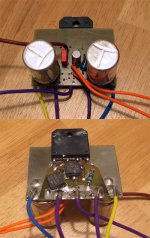
I'm pretty convinced that they are nowadays but I would like to see a picture with the lid lifted off, which apperently not is easy...BrianGT said:picture from gaincard
BrianGT said:picture from gaincard
Ugly.

Fedde's board is better, doesn't look like made in the kitchen just before dinner.

But ultimately, I just don't like these boards.

Re: pictures from gaincard
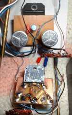
The soldering looks much better here than on their integrated amp. Also notice that the copper traces are rounded as much as possible. The components have large contact areas with the copper trace, looks like the end of the resistors are bent in the back and don't just stick out of a hole.
I'm puzzled why they don't use a small circuit board. They could have the exact same traces and holes. I'd also worry about the oxidization of copper.
Jamh said:I'm puzzled why they don't use a small circuit board.
Looks to me like they already are using a small circuit board. What am I overlooking?
They could have the exact same traces and holes.
Why? They apparently already have a circuit board with the traces and holes right where they want them.
I'd also worry about the oxidization of copper.
Why? I don't see any problem unless you planned to use it in a marine environment or something.
se
- Status
- Not open for further replies.
- Home
- Amplifiers
- Chip Amps
- internals 47 labs 4717 integrated