Nope, but it's probably one of the few things in academic life I may actually have been good at had I pursued that path... I wouldn't have been a prime PhD candidate from a research aspect. Always found keeping track of sources a real chore. In hindsight, maybe I should have tried anyway, things didn't go all that well out in the wild...Are you a teacher Sir?
I could just about see +11.25 V on +/-12.0 V happening with a bit of a following wind, but +11.75 with that architecture? No way. You've got one transistor Vce,sat (0.05-0.2 V maybe) + one transistor Vbe (0.55-0.65 V) between your V+ and output, so I can't imagine you'd get closer than 0.6, probably more like 0.7-0.8 V.I may trust NJM2043 for that. I used it by accident with +-12v supply and 11.75V output offset and it still worked, while i tried a whole lot of other op-amps with same offset and none of them worked. I suspect NJM4556(maybe njm2068 too) can do the same trick as they are all using the same type of output stage.. BTW NJM2043 max supply is +-22v and it's ability to drive 400 ohm loads is really useful.
Counting pixels in the datasheet graphs, the minimum I can find is maybe 0.6 V at 100 µA out, rising to maybe 0.8 V at 1 mA out. Rather more on the negative side. No indication of anything even close to 0.25 V - it's a physical impossibility. The output transistor wouldn't be doing squat with Vbe that low, which can't be given its non-zero bias current.
NJM2043 driving abilities look much the same as the NJM2068's. The older part does seem to exhibit appreciably lower voltage noise (about 3 dB less), but in turn its input bias current is roughly double as well.
Sijosae got 6.1 Vpp out of an NJM4556 on a 9 V supply when ~unloaded (several kOhms, I think a 4k7/1k cMoy), 5.9 Vpp with a 330 ohm load. Interestingly, a bunch of 4558s and 5532s along with NJM072 and AD712 scored slightly higher in the unloaded test (6.2-6.4 Vpp), all of them edged out by the NJM4580 at 6.6 Vpp, in turn displaced by OPA213x at 7.3 Vpp, OP27 at 7.4 Vpp and AD8620 (a +/-13 V part) at 7.5 Vpp - and then there were the two RRO parts TDA1308 (actually operated beyond spec) and AD823 at 8.7 Vpp each. By contrast, OPA2604 only made it to a measly 4.6 Vpp, OPA627 got to 5.3 Vpp, and LM833 and AD826 at 5.5 Vpp weren't much better.
As you can see, 2 V from the rails with realistic loading is a pretty safe bet, a fair few parts will also get to within 1.5 V, but only a handful to with 1 V. RRO parts should get to within 0.2 V quite reliably.
So, with my CFP transistor design, I need to select resistors. Naturally, I would like them matched, but the question is: How close is close enough? 1% tolerance resistors are 10¢ apiece, 0.1% resistors are 3 to 5 times that.
Last edited:
As i said already i discovered that by accident with some njm2043dd i bought from Mouser last year and no other op-am i tried worked with same output offset(i tried about 8 different op-amps up to opa2228).It costs you less than 1 dollar to check that.No indication of anything even close to 0.25 V - it's a physical impossibility. The output transistor wouldn't be doing squat with Vbe that low, which can't be given its non-zero bias current.
Last edited:
As i said before in some other places njm 2068, njm2041 and njm2043 are a natural bias vs input noise progression( 300k, 200k, 100k= Zin vs lower noise for lower source impedances) They don't make the njm2041 anymore, but it was used intensively in Fostex mixing gears.NJM2043 driving abilities look much the same as the NJM2068's. The older part does seem to exhibit appreciably lower voltage noise (about 3 dB less), but in turn its input bias current is roughly double as well.
If you are going to hand-match them anyway (multimeters with sufficient resolution are quite common these days), you may be better off buying a bunch of 1% parts. We are much more interested in relative variation than absolute tolerance in this application. And even the cheapie Yageo metal films exhibit very little excess noise (though more posh brands have even less to offer).So, with my CFP transistor design, I need to select resistors. Naturally, I would like them matched, but the question is: How close is close enough? 1% tolerance resistors are 10¢ apiece, 0.1% resistors are 3 to 5 times that.
Out of the batch of 10 random Chinese metal films measured here, you could make two excellent pairs (within <0.1%), one good pair (0.1%) and would have two semi-OK pairs left for other, less critical applications (0.5%, 0.7%). The bigger the batch, the more likely a match. (It even rhymes! 😀) This should even apply if the parts have been cherrypicked for 0.1% ones already, since again we are looking for relative matches.
So even if you only end up using half the resistors, it still ends up being more economical than the 0.1% parts, and you have a bunch of spare resistors for random projects or single-ended circuitry left in the bin. (We haven't looked at what other parts of the mixer might benefit from modding yet.)
BTW, when absolute value isn't too critical, buying oddball values of precision resistors is an old cost-saving trick - the more mainstream values tend to be more expensive.
Good point!!If you are going to hand-match them anyway (multimeters with sufficient resolution are quite common these days), you may be better off buying a bunch of 1% parts. ........since again we are looking for relative matches.
So, what's your opinion----are Elna Silmics for power supply bypass capacitors worth the money?
I can't believe you asked that...Good point!!
So, what's your opinion----are Elna Silmics for power supply bypass capacitors worth the money?
As in, say, the RC filters on each board?Good point!!
So, what's your opinion----are Elna Silmics for power supply bypass capacitors worth the money?
Honestly, I doubt it. Silmics are something that I might use as a coupling cap in the actual signal path. (Not to mention they sort of strike me as semi-snake-oil. They are solving a microphonics problem that isn't really there in the first place.) Power supply decoupling on something with actually half-decent PSRR isn't such a subtle job.
I looked it up, and the price of ten Silmic II 100µ/35V caps on Mouser roughly equals the same amount of 220µ/63V, 390µ/50V or 470µ/35V Panasonic FCs. Likewise, instead of 47µ/35V Silmics you could get 270µ/50V FCs, or 330µ/35V, 220µ/50V, 150µ/50V or 100µ/63V FRs. I would go with more capacitance and lower ESR any day of the week.
Don't sweat it too much in general. What you've got in there now is 35+ years old and has probably seen better days if the console was used a lot. A lot of good-quality caps would work fine and last for many years.
If you still need inspiration for some big can-type caps, this thread discusses several.
You should go through the schematic and identify caps that are critical, particularly:
* polar electrolytic caps that never see much of any DC at all (these are quite likely to be degraded at this point; I might even consider explicit low-leakage parts for them) - a lot of the coupling caps would qualify
* film caps in the signal path, particularly >1 nF (I think most of these are in the input EQ)
Yeah, the Elna brochure's touting sorta smells of audiophool hype:Silmics....... sort of strike me as semi-snake-oil. They are solving a microphonics problem that isn't really there in the first place.)
"Due to the silk fiber's pliability, the capacitor makes a dream of the high quality sound. For examples ;
● To relieve the music's vibration energy.
● To decrease the peak feeling sound at high compass and rough quality sound at middle compass.
● To increase massive sound at low compass."
I will be replacing ALL signal-path electrolytics with bi-polar Nichicon MUSE caps, as they are reported to have extremely low distortion (Nichicon Muse ES bipolar caps measured: <-120dB THD, <-140dB IMD) and are actually 25% LESS expensive than the SILMICsYou should go through the schematic and identify caps that are critical, particularly:
* polar electrolytic caps that never see much of any DC at all (these are quite likely to be degraded at this point; I might even consider explicit low-leakage parts for them) - a lot of the coupling caps would qualify
* film caps in the signal path, particularly >1 nF (I think most of these are in the input EQ)
The polyester caps in the input EQ will be replaced by WIMA polypropylenes.
Yamaha, Nakamichi, Pioneer and Sony knew that 30 years ago 🙂I will be replacing ALL signal-path electrolytics with bi-polar Nichicon MUSE caps, as they are reported to have extremely low distortion (Nichicon Muse ES bipolar caps measured: <-120dB THD, <-140dB IMD) and are actually 25% LESS expensive than the SILMICs
The usual Polyester foil that you find in any filter section of the 90's equipment might audibly perform better than metalized polypropylene ... That's something that you learn the hard way...Polypropylene dielectric used to be squeezed at much finer thickness than polyester because of its better specs, thus you get some piezo effects ...Some use higher voltage polypropylene as its having thicker dielectric and better damping , but then you have the same losses as in polyester foil when used with lower signals while foil is handling better the signals than metalized ones...So in the end you find out that the ubiquitous polyester foil is just fine...
Perhaps you missed it, but the OP showed a graph (post #1) of better than -10db of THD improvement with Wima FKP cap replacement.
fkp is polypropylene foil not metalized poly...i'm using them too mostly for compensation .I find wima's too bright sounding when used as coupling , i prefer the polyester caps...I don't need to hear intermodulation products due to ultrasonic oscillations...
Last edited:
Now, I'm trying to figure out the rest of the Soundcraft 200's circuitry. Following the mic pre is the EQ circuit--they used JFET TL072s there, which makes sense as FETs are better for EQ circuits. But, for the summing busses and output circuits, they switched to NE5532s. Hmmmm.....The TL072 is a little faster (13v/µSec) vs. the 5532(9 v/µSec); they have identical THD specs, and noise doesn't really matter once you get to line level. The NE5532 was probably a little more $$$, so why the switch? Is there an advantage of bipolar ICs in those applications? They also used the TL072s in the tape return circuitry. ??????
Good point! I hadn't realized the TL072 was so poor at driving loads until I looked beyond the normal data sheet listings (where drive current is NOT listed) to the graphs, where it showed the TL072 has difficulty driving anything below 10K Ω.n5532 has more drive...
...noise doesn't really matter once you get to line level....
The summing mixer gains-up hiss by the number of inputs. 8-in mix has a 18dB noise penalty. You need significantly more then 18dB gain before the sum network to avoid adding hiss.
The lower hiss Voltage of '5532 is better here. High-buck mixers go further.
Your questions lead to Douglas Self's Small Signal Audio 2010 et al.
How about an LM4562? Lower noise (2.7nV√Hz vs. 5nV√Hz). Lower current drive in the 4562(26mA) vs. 5532 (38mA), but is probably enough? Typical load would be a tape machine, audio processor, or monitor amplifier---normally ~10KΩ loads, but possibly 600Ω. Peak signal of 15 volts into 600Ω is 25mA.The summing mixer gains-up hiss by the number of inputs. 8-in mix has a 18dB noise penalty. You need significantly more then 18dB gain before the sum network to avoid adding hiss.
The lower hiss Voltage of '5532 is better here. High-buck mixers go further.
Last edited:
 My crude drawing of my Soundcraft Mic Pre. Comments? I'm showing a TL072 (available in SiMetrix) but will use an OPA1642.
Last edited:
Why using smd componets? Go with opa2132 or opa2228 there, but i doubt you'll hear a difference !
Basically looks good. You missed the 3k3 input resistor (R46 or R45?), Q2/4 are likely to be a waste of some perfectly good ZTX450s, there is no reason not to leave R7/9 at 4k7 (or is that supposed to be the combination of 3k9+470 || 4k7?), and you could go down to 1k-1k5 for R3/10 to get the common-mode swing down at this point, but other than that...
I noticed that on the input board, IC2 would be very much worth swapping out for something with more oomph as well... the poor TL072 has to be driving 3 10k pots in parallel plus a bit, that's not going to go down too well if you are trying to run the input amp hot.
I've been going through the rest of the mixer, and while I can't puzzle together a typical signal routing just yet (I should probably just RTFM thoroughly), I noticed a whole bunch of ground-compensated output amps like this:
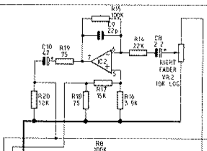
100k/22k after a 10k pot (Rout = 2k5 max)? Maybe they didn't want to bend the pot curve too much or something, or the circuit had originally intended to be used with a TL072 rather than the 5532 they ended up using. In any case they're wasting several dBs of noise there. And unless I missed something, the divider ratio of 16k/3k9 in the ground compensation does not match 100k/22k too well either... why didn't they go with e.g. 10k/2k2 instead?
Oh crap. With the pot in front, the divider ratio in one leg is slightly variable. At the worst-case 2k5 source R (6 dB down from max), the divider ratios are an almost perfect match. Elsewhere they're slightly off, so cancellation of ground loop noise when going into an unbalanced input would be reduced but still partially effective.
Maybe I'll find a lower-noise option in sim, but other than that it'll be hard to get output amp noise down effectively. On the upside, at this stage signals should be plenty strong anyway.
EDIT:
I noticed that on the input board, IC2 would be very much worth swapping out for something with more oomph as well... the poor TL072 has to be driving 3 10k pots in parallel plus a bit, that's not going to go down too well if you are trying to run the input amp hot.
I've been going through the rest of the mixer, and while I can't puzzle together a typical signal routing just yet (I should probably just RTFM thoroughly), I noticed a whole bunch of ground-compensated output amps like this:
100k/22k after a 10k pot (Rout = 2k5 max)? Maybe they didn't want to bend the pot curve too much or something, or the circuit had originally intended to be used with a TL072 rather than the 5532 they ended up using. In any case they're wasting several dBs of noise there. And unless I missed something, the divider ratio of 16k/3k9 in the ground compensation does not match 100k/22k too well either... why didn't they go with e.g. 10k/2k2 instead?
Oh crap. With the pot in front, the divider ratio in one leg is slightly variable. At the worst-case 2k5 source R (6 dB down from max), the divider ratios are an almost perfect match. Elsewhere they're slightly off, so cancellation of ground loop noise when going into an unbalanced input would be reduced but still partially effective.
Maybe I'll find a lower-noise option in sim, but other than that it'll be hard to get output amp noise down effectively. On the upside, at this stage signals should be plenty strong anyway.
EDIT:
He said OPA213x had become rather too expensive for his tastes. Also, with those 100ps I reckon a unity-gain stable part would be good, so OPA2227 instead of 2228.Why using smd componets? Go with opa2132 or opa2228 there, but i doubt you'll hear a difference !
Attachments

Last edited:
- Home
- Source & Line
- Analog Line Level
- Interesting Soundcraft 1600 mod results