If I use a transistor with rbb=5Ω, and a 15Ω in-series-with-pot resistor, it would indeed give me ~ 1db improvement---as you say, not much---but added up over 8 channels, it might make a difference, eh?....Let's say you can tweak the circuit and get things down by 30-50 ohms - you'll gain half a dB at 150 ohms, maybe even close to a full dB with a bit of a following wind. When was the last time one whopping dB of noise made a night-and-day difference to you? (*crickets* Yeah.) Diminishing returns for sure.
Alternatively, 10k/33Ω would yield a gain very similar to pre-mod condition. If we say that the improved linearity would buy us a few dB on top, I'd try roughly 18-20 ohms (4-5 dB more gain than pre-mod seems manageable).
Again, I am not following your math. The pre-mod gain was 22K/33Ω=~ 56.5db. 10K/33Ω would give 49.6db, a 7 db decrease. 10K/15Ω would give 56.5 db; exactly the same. If you think that 18Ω would yield more linearity, OK---that would give a gain of 54.9 db---certainly close enough.
Last edited:
1 dB less noise over 8 channels is 1 dB less noise mixed together.
If you want, you can try posting your level settings and we can try to figure out whether your gain staging makes any sense at all.
Your gain calculation is off by a factor of 2, and you forgot to include transistor re as well. This adds Vt/Ic per transistor to the 33R, for ~85 ohms total. Guess what, 20 log(2x 22k/85) = 54.2 dB.
The CFP mod (with 6k87 resistors) effectively reduces re to ~1 ohm a pop thanks to feedback, and 22k/35R gives 62.0 dB (sim says 61.4 dB). So that mod alone increases gain by about 8 dB! For 10k/20R, ~59 dB is expected (sim says 58.6 dB).
You are, of course, correct---when I do the math---i.e., adding the noises by taking the square root of the sums of each channel's noise squared, I get the same----1 db. Doesn't seem intuitive to me (seems like adding more and more less-noisy channels would LOWER the noise), but that's not what the math says1 dB less noise over 8 channels is 1 dB less noise mixed together.
I'm not sure what level settings will be at this point----varying between a Shure microphone-----1.6mV (output from a 94 db SPL source) at 310Ω source impedance----- to a Neumann mic with 8 mV at 150Ω.If you want, you can try posting your level settings and we can try to figure out whether your gain staging makes any sense at all.
Yes, I see my errors now; my new calculation is 59.2 db max gain with the 10K/20R. I'm learning!Your gain calculation is off by a factor of 2, and you forgot to include transistor re as well. This adds Vt/Ic per transistor to the 33R, for ~85 ohms total. Guess what, 20 log(2x 22k/85) = 54.2 dB.
The CFP mod (with 6k87 resistors) effectively reduces re to ~1 ohm a pop thanks to feedback, and 22k/35R gives 62.0 dB (sim says 61.4 dB). So that mod alone increases gain by about 8 dB! For 10k/20R, ~59 dB is expected (sim says 58.6 dB).
I also calculated a gain plot using the existing 10KΩ reverse-log pot---comes out showing the gain graduations to be heavy on one side; a 5k pot would show almost the same as original, with just that extra 5 db at the very top. But that's just being picky.
Not to mention the considerable variations in sound source level and distance. For speech recording, I might be using somewhere around 50-54 dB for the Shure and 40 dB for the Neumann.I'm not sure what level settings will be at this point----varying between a Shure microphone-----1.6mV (output from a 94 db SPL source) at 310Ω source impedance----- to a Neumann mic with 8 mV at 150Ω.
This might be easier to tackle from the output side of things. I am running my small mixer into consumer line level (0 dBFS = +8 dBu) inputs, and my output gain tends to be about -10 dB, so I'm shooting for about +18 dBu peak internally.
Making a dial would certainly be helpful in practical use. You can calculate max and min gain, the rest shouldn't be too hard to determine by measurement (relative digital recording levels) from there.I also calculated a gain plot using the existing 10KΩ reverse-log pot---comes out showing the gain graduations to be heavy on one side; a 5k pot would show almost the same as original, with just that extra 5 db at the very top. But that's just being picky.
My mixer's outputs feed an analog tape machine (I'm old-school!) that operates at 1 volt rms= 0 V.U. (I never really liked the one milliwatt into 600 Ω = 0.775 volts= 0 dbm thang; 1 volt into 1 K Ω= 1 milliwatt= 0 dbV makes a hell of a lot more sense to me) So all my gear runs at a 0 dbV nominal level with 18 volt rails, giving me ≥24 db of rms-to-peak headroom.
Back to my CFP mic preamp, I was perusing the THAT presentation and the Rod Elliott design. THAT indicates that the low-gain noise sources are dominated by the thermal noise of the collector and emitter resistors, as well as the opamp EIN and the shot noise of the transistors. Which leads me to believe that these should be as low as possible. Rod uses 2.2KΩ collector resistors whilst THAT uses 750 Ω; you have indicated 6.87K Ω. THAT also lowers the emitter resistors to 2.87K Ω, while the existing circuit, you, and Rod have 4.7K Ω. Can you explain this to me?
Back to my CFP mic preamp, I was perusing the THAT presentation and the Rod Elliott design. THAT indicates that the low-gain noise sources are dominated by the thermal noise of the collector and emitter resistors, as well as the opamp EIN and the shot noise of the transistors. Which leads me to believe that these should be as low as possible. Rod uses 2.2KΩ collector resistors whilst THAT uses 750 Ω; you have indicated 6.87K Ω. THAT also lowers the emitter resistors to 2.87K Ω, while the existing circuit, you, and Rod have 4.7K Ω. Can you explain this to me?
Last edited:
That's oldschool alright. 😉 I would still like to have a fast-acting peak level meter somewhere. Any clue where the best-case (300 Hz - 1 kHz) saturation limit is for your tape material?My mixer's outputs feed an analog tape machine (I'm old-school!) that operates at 1 volt rms= 0 V.U. (I never really liked the one milliwatt into 600 Ω = 0.775 volts= 0 dbm thang; 1 volt into 1 K Ω= 1 milliwatt= 0 dbV makes a hell of a lot more sense to me) So all my gear runs at a 0 dbV nominal level with 18 volt rails, giving me ≥24 db of rms-to-peak headroom.
Your headroom calculation is a bit optimistic, I think. I would not trust the average opamp to swing much closer than ~2 V from the rails, and in the Soundcraft 200 you're only looking at a nominal 17 V minus a bit for RC filtering, so let's say +/-16 V. Realistically, that leaves about 10 Vrms with a bit of a following wind. Samuel Groner already got a TL071 to about +22 dBu on +/-15 V, so maybe half a dB more. Anyway, 20-20.5 dB of headroom is about it.
That should generally do but it's not that hard to generate sounds with higher peak/average ratios, I think. The drum kit would contain a few potential candidates. Handling plates and cutlery tends to account for some major peaks during ambient recordings here. I'm not even counting clapping. (I've been using that for gauging worst-case levels and setting gains in a way that would not clip anything.)
First off, I think you've got your collectors and emitters upside down.Back to my CFP mic preamp, I was perusing the THAT presentation and the Rod Elliott design. THAT indicates that the low-gain noise sources are dominated by the thermal noise of the collector and emitter resistors, as well as the opamp EIN and the shot noise of the transistors. Which leads me to believe that these should be as low as possible. Rod uses 2.2KΩ collector resistors whilst THAT uses 750 Ω; you have indicated 6.87K Ω. THAT also lowers the emitter resistors to 2.87K Ω, while the existing circuit, you, and Rod have 4.7K Ω. Can you explain this to me?
Among the emitter resistors, you've got (2x Re = 2x 6.87k) effectively in parallel to (Rgmin + Rpot = 33R + 0...10k). For all but the lowest gain ranges, the latter term is going to dominate, being much smaller. Not much of a noise issue right there.
Among the collector resistors, a markedly lower value would actually increase noise and distortion at higher gains somewhat (the latter particularly without CFP), as gain is shifted away from the input pair and towards the opamp. At some point opamp input voltage also leaves permitted common-mode input voltage range, which e.g. for TL07x starts at 3 V from the negative rail, so I_leg * (Rc||Ropamp) >3 V is required.
That said, a moderate reduction to 3k3 or 2k2 would benefit handling of high input levels at minimum gain, as otherwise input transistor C-E voltage can become very low in the peaks. After all, 4k7 collector was originally chosen to be paired with 15k emitter, and voltage drop over Rc is much increased with 6.87k. 8.2k or at least 7.5k looks like a safer bet now. I think I originally didn't simulate at output amplitudes quite as high (like 8Vp rather than 12Vp) - my bad, sorry.
So you can see that for a given tail current (Vsupply / Re), there is both an upper and lower practical limit for Rc. In between, you are basically free to choose. As long as opamp inputs are at -6 to -12 V or so, you should be OK.
Mind you, if you do consider swapping out the 4k7 array Rcs, you might just as well go for broke and further increase LTP tail current altogether. While every mA counts, 2k87 emitter resistors would give you over 10 mA of tail current (plus opamp), which is perhaps a bit rich for my blood. I would go for more like 5-6 mA, which would be 4k7-5k6 on the emitter. 1k5-1k8 on the collector would work for both. Hmm. At the same time, further increased current does reduce distortion at high output levels / near max gain a fair bit more.
Just an idea - what if you don't mod all the inputs the same? You could have maybe one or two "hotties" along the lines of what THAT suggested for dynamic mics, and then one or two with a "minimal invasive" mod with only minimally increased current consumption but still a good bit less distortion if maybe a smidge higher noise (with an electret, who cares?).
"Hot" resistor values, top to bottom as appearing in schematic:
Re* | Rgmin | Rcfp | Rc*
2k87(...3k3)* | 20R | 470R | 1k*
"Minimal invasive", top to bottom:
8k2* | 33R (stock) | 1k2 | 4k7* (stock)
Opamp: 10k+10k* each
same CFP for both
* matched
Noise in the "minimal invasive" version is slightly higher as the input transistor has to make do with a "measly" 580 µA instead of a full mA - it still computes to about -132 dBu shorted (2N4403 input), or just about as low as any other decent mixer. At the same time, distortion is already down by almost 30 dB in the higher gain ranges, partly because the current diverted from the input transistor benefits the second one.
Simulated distortion - 100 mVrms in, 40 dB gain (200R/2x10k), 3rd harmonic:
BJT only "2 mA" -43 dB (nice fx box),
BJT only "all original 400R / 2x22k, 2 mA" -59 dB,
CFP "minimal invasive" -71 dB,
CFP "minimal invasive but higher input Q @ 1 mA / Rcfp=680R" -58 dB,
CFP "5 mA / Re=5k6" -79 dB,
CFP "6 mA / Re=4k7" -86 dB,
CFP "6 mA / Re=4k7 but lower input Q @ 600 µA / Rcfp = 1k2" -91 dB,
CFP "hottie" -103 dB (probably below TL07x contribution).
BJT only "hottie 10 mA 200R/2x10k" -86 dB
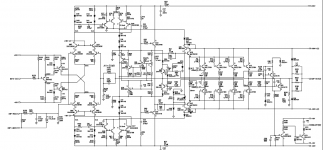
Yeah, I got one of those, and it's NOISY as hell!because we had other discussions on the subject here you have a hand drawing of the input stage for Tascam Portastudio 414 based on njm2068SD
Yeah, I LOVE my old tape recorders---My 8-track machine is Dolby SR-equipped, so I have S/N ratio of ~ 90 db---almost as quiet as 16-bit digital; but a hell of a lot better sounding.That's oldschool alright. 😉 I would still like to have a fast-acting peak level meter somewhere. Any clue where the best-case (300 Hz - 1 kHz) saturation limit is for your tape material?
I’ve never actually measured the point of total tape saturation; we always kinda set +9db over operating level as maximum, because that’s where the third harmonic distortion reaches 3% with modern tapes. Above that, analog tape just pretty much compresses the signal. Funny thing about clipping and tape saturation---I was working post-production on a TV show (many moons ago; I think it was NYPD Blue). The sound man in this case was running two recording machines---one digital (a DAT) and one analog (a Nagra) ----maybe to see if there was a noticeable difference in sound quality, or maybe just as a backup in case one failed. In one particular scene, the actor jumped from one platform to another, which was about 10 feet lower. The microphone was fairly close. Needless to say, that created a very loud THUMP which of course PINNED the meters on both machines. Back at our post house, we played both tapes from this scene---the digital machine went to FF at the thump part and was totally distorted—an awful, unusable sound. The analog machine, however, just sorta did a “soft” compression of the thump---distorted somewhat, sure, not unpleasantly so, and totally usable. An excellent example of the difference between analog and digital audio recording. Somewhat similar to Class-D power amplifiers---I use them to great advantage in many applications, but you NEVER want to reach clipping---it sounds absolutely horrible.
Maybe. But, in my power supply modification, I'll probably raise the rails slightly to +/- 18 volts. And I will definitely get rid of those awful TL072s in favor of rail-to-rail OPA16xxs. So I'm confident of having plenty of headroom.Your headroom calculation is a bit optimistic, I think.
Yes, my bad.First off, I think you've got your collectors and emitters upside down.
That's a VERY interesting idea. Unfortunately, my test gear probably isn't good enough to measure the differences, so I'll have to go by ear.Just an idea - what if you don't mod all the inputs the same?
I'm still mulling over the resistor changes and their effect.
Here's a really stupid question----I'm reading Rod Elliott's article on his mic preamp, and noticing that he claims noise performance of 1.9nV√Hz. The NE5532 he employs is only rated at 5nV√Hz. How does the CFP actually LOWER that noise?
> 1.9nV√Hz. The NE5532 he employs is only rated at 5nV√Hz. How does the CFP actually LOWER that noise?
Gain before the noisy part.
If you have hiss=5, and can put a *perfect* (hissless) gain of 2.5 in front, the hiss is now at 2. These transistor-in-front-of-opamp plans usually take LOTS of gain in the transistors (you could figure that), using the opamp for DC-shift, load-drive, and NFB reserve.
Gain before the noisy part.
If you have hiss=5, and can put a *perfect* (hissless) gain of 2.5 in front, the hiss is now at 2. These transistor-in-front-of-opamp plans usually take LOTS of gain in the transistors (you could figure that), using the opamp for DC-shift, load-drive, and NFB reserve.
Hmmmm....but if you hook up an NE5532 as a unity-gain buffer, and short the inputs, don't you still have the 5nV√Hz (707nV rms) noise? No current noise or Johnson noise, of course. Does the "perfect hissless gain" suck the noise down?> 1.9nV√Hz. The NE5532 he employs is only rated at 5nV√Hz. How does the CFP actually LOWER that noise?
Gain before the noisy part. If you have hiss=5, and can put a *perfect* (hissless) gain of 2.5 in front, the hiss is now at 2.
Yep, sounds about right. Studio personnel sure had a bit of rethinking to do in the early days of digital. It doesn't help when you hit analog snags like opamp phase inversion.An excellent example of the difference between analog and digital audio recording.
The first commandment of digital recording:
Thou shalt not clip.
Oh, that's interesting. Worse than traditional AB jobs?Somewhat similar to Class-D power amplifiers---I use them to great advantage in many applications, but you NEVER want to reach clipping---it sounds absolutely horrible.
I don't think it's particularly advisable to operate parts rated at +/-18 V abs max this close to their limits. I'd rather want to explore the extra "footroom" opened up by their lower voltage noise and better driving abilities.Maybe. But, in my power supply modification, I'll probably raise the rails slightly to +/- 18 volts. And I will definitely get rid of those awful TL072s in favor of rail-to-rail OPA16xxs. So I'm confident of having plenty of headroom.
RF designers discovered the advantages of this approach in the '80s - it resulted in FM tuner frontends much less prone to overload. After all, it does not really matter where your dynamic range is (level wise) as long as you can translate it to the outside world. DACs these days are getting 120+ dB of dynamic range out of a single +5 V analog supply.
Remember, dynamic range is the ratio of signal power to noise power. At constant power, you can vary the ratio of voltages and currents - AKA impedance - to suit voltage and current noise sources as well as driving abilities of available circuitry. 1 Vrms into 1 kOhm is equivalent to 10 Vrms into 100 kOhms or 0.1 Vrms into 10 ohms, and every resistor has the same thermal noise power on offer.
That's why vacuum tube circuits tend to have literal input and output transformers. Their input voltage noise may be super high (from what I've read, densities of 40..100 nV/√(Hz) within the audible range are anything but uncommon - if you want to know more about this, Burkhard Vogel is your man) but there's barely any input current with its associated noise since they are capacitive devices, and while plate currents tend to be rather modest, they can handle substantial voltages.
BTW, TL07x are not "awful" at all as long as you know how to use them properly - which is to say inverting with output loading of minimum 10 or even 20 kOhms at high levels. They are geared towards the higher end of the impedance spectrum. Not to mention being the better part of 50 years old.
As PRR has already stated: It provides no shortage of gain. If we are assuming the opamp to "hold still" for a moment, it would be 2*Rc/[(Rgmin+Rpot+2*Re,cfp)||2*Re], or at maximum gain, ~=2*Rc/(Rgmin+2*Re,cfp) ~= 2*Rc/Rgmin. With Rc =1k, that's easily still 20 dB at a 40 dB total gain setting, or 30 dB at 50 dB. The opamp is then burdened with the rest. (The Rc term never makes an appearance in total gain because it cancels out. It just influences the distribution of gain between input stage and opamp.)Here's a really stupid question----I'm reading Rod Elliott's article on his mic preamp, and noticing that he claims noise performance of 1.9nV√Hz. The NE5532 he employs is only rated at 5nV√Hz. How does the CFP actually LOWER that noise?
Quoting verbatim from Gain Staging for Dummies,
Nabbing the formula for total equivalent input noise and applying it for two stages:yours truly said:A device with multiple stages of varying noise level and gain is a classic application of Mr. Friis. In a voltage matching scenario as commonly used in audio (read: load impedance much higher than (>>) source impedance), formulas are slightly different but analogous.
e_n,eq² = e_n,1² + e_n,2² / G_1²
IOW, effective input noise of both stages is RMS summed with the second stage's contribution being reduced by first-stage gain. Which is logical if you consider that at the second stage input, its noise RMS sums with first stage noise multiplied by first stage gain. Divide the whole shebang by first-stage gain to obtain effective input noise.
Let's say e_n,1 = 1.3n, e_n,2 = 13n, G_1 = 30 (so that's not even full tilt). Total e_n,eq = 1.37n.
(It's a good thing I did this - I promptly spotted an error in my formula! Now rectified.)
Now I hope this all still holds even though the input pair is a transconductance amplifier (high-impedance current output = "open") and the opamp forms a transimpedance amplifier (low-impedance current input = "short"), so it's a current-mode interface.
In a way, this setup could be likened to a folded cascode, although just for differential mode. The opamp has super low input impedance for differential mode but does not care about common mode at all, leaving only its associated resistors for common-mode input impedance. Hmm, I wonder whether common mode could be servoed out somehow, and whether there would be any benefit doing so...
Last edited:
Somewhat similar to Class-D power amplifiers---I use them to great advantage in many applications, but you NEVER want to reach clipping---it sounds absolutely horrible.
MUCH worse to my ears. Not that traditional AB clipping sounds GOOD, mind you; but to me, it's MUCH less offensive than digital clipping, which is absolutely intolerable.Oh, that's interesting. Worse than traditional AB jobs?
I'm still trying to understand this; but with your VERY complicated answer, I guess it wasn't such a DUMB question after all!😀IOW, effective input noise of both stages is RMS summed with the second stage's contribution being reduced by first-stage gain
> don't you still have the 5nV√Hz (707nV rms) noise?
Yes.
You may be mixing Input Hiss with Output Hiss. Are you thinking "referred to input"?
Yes.
You may be mixing Input Hiss with Output Hiss. Are you thinking "referred to input"?
Well, with how in-depth we have been getting here, I'd have thought that you'd have (more or less) understood this earlier.I'm still trying to understand this; but with your VERY complicated answer, I guess it wasn't such a DUMB question after all!😀
And BTW, I only explained in-depth what PRR had already mentioned earlier.
In a nutshell, if the low-noise stage preceding your opamp has so much gain that its output noise totally swamps opamp noise, that in turn becomes much less important.
On a related note, I've been working on an RMS summing and unsumming calculator today. If you've always wanted to know what kind of input voltage noise density an input has if it is given with an EIN of -128.5 dBu @ 150 ohms, 20 kHz bandwidth, or what the RMS sum of -120 dBV, -126 dBu and 0.85 µVrms might be, these should be right up your alley. Sure beats a scientific calculator orgy. Let me know whether there are any obvious candidates for extra features or even bugs.
I am wondering if replacing the coupling electrolytic capacitors with bi-polar caps (Nichicon MUSE) would make an even-further reduction in distortion.I've been slowly recapping and modding my Soundcraft 1600 console, and have some interesting measurement results I thought I'd share.
Mods done to channel strips are: Recapped electros with Panasonic FC
The distortion figures are pretty interesting. Going to Panasonic FCs gave a good reduction in distortion over stock, until we get to the top end which is actually a bit worse.
Are you a teacher Sir?And BTW, I only explained in-depth what PRR had already mentioned earlier.
I never found such clear explanations as the ones you made in this topic for what i really wanted to know for a long time.Thank You SIR!
This is really GREAT!On a related note, I've been working on an RMS summing and unsumming calculator today. If you've always wanted to know what kind of input voltage noise density an input has if it is given with an EIN of -128.5 dBu @ 150 ohms, 20 kHz bandwidth, or what the RMS sum of -120 dBV, -126 dBu and 0.85 µVrms might be, these should be right up your alley. Sure beats a scientific calculator orgy. Let me know whether there are any obvious candidates for extra features or even bugs.
When Mackie launched their VLZ1402 mixer it was meant as sound reinforcement along VLZ1400 amplifier for small parties , but soon after that got into recording studios when people observed its performances.
A bit of "Mackie offtopic " 🙂 :
VLZ1400 amp is also a beast by all means and very unique too! I still remember when i heard for the first time some active Mackie speakers in an underground show and what really impressed me was how clear was it at insane powers levels. 2x 400w RMS were litterally blasting my ears in a confined space and i couldn't feel ear fatigue, while some poor 30w bass systems feel like killing my ears most of the time.Till today that sounded like the best show sound reinforcement i ever heard.Like my other favorite Kenwood L series amplifiers VLZ1400 exhibit very high damping factor and i think that was the motif for not feeling that base fatigue at very high powers.
Attachments
Last edited:
I may trust NJM2043 for that. I used it by accident with +-12v supply and 11.75V output offset and it still worked, while i tried a whole lot of other op-amps with same offset and none of them worked. I suspect NJM4556(maybe njm2068 too) can do the same trick as they are all using the same type of output stage.. BTW NJM2043 max supply is +-22v and it's ability to drive 400 ohm loads is really useful.I would not trust the average opamp to swing much closer than ~2 V from the rails,
- Home
- Source & Line
- Analog Line Level
- Interesting Soundcraft 1600 mod results