we often forget this
very good transformer at low price.
Ogonowski.eu - profesjonalne transformatry do wzmacniaczy lampowych
very good transformer at low price.
Ogonowski.eu - profesjonalne transformatry do wzmacniaczy lampowych

To measure the 1100v PSU, I used 4x 220K 1% resistors in series. Measure between one resistor and ground and multiply the measured voltage by 4.
Be careful and isolate well everything. Make sure the solder joints are rounded, without sharp spikes. Keep a good distance between HV parts and ground to avoid arcs.
Be careful and isolate well everything. Make sure the solder joints are rounded, without sharp spikes. Keep a good distance between HV parts and ground to avoid arcs.
I will be using 2.5 cm spacers for b+ board... Screwed on the chassis, as you didTo measure the 1100v PSU, I used 4x 220K 1% resistors in series. Measure between one resistor and ground and multiply the measured voltage by 4.
Be careful and isolate well everything. Make sure the solder joints are rounded, without sharp spikes. Keep a good distance between HV parts and ground to avoid arcs.
And when b1+ working, I'll cover the rear part with some epoxy resin
My GM70PP amp HT has 3 caps in series with bleeder resistors. I measure the bottom one and then x3. No need to have seperate string just for measurements.
Mine also has 3 caps in series with bleeder resistors, but they are well isolated /covered (better safe than sorry) so I can't measure at that point - that's why I have to use an external resistor series.
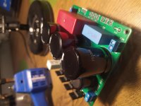
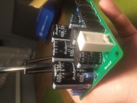
Hello friends, for those of you who didn't forget this project, the works go on. 😀
Built and tested psu boards, we got nice 1100V B+.
Next step is adding cable receptacles (Amphenol) and building cables of a suitable length.
Still awaiting that Rod ultimates his testing on bias regulator, while Ale Moglia's boards are populated.
Then will be time to start with the audio case, and displace the massive russian caps...
To measure B+ had to put in series 10x 100k resistors, tried with 4x330k and 4x220k, but voltage readings with my 2 multimeters didn't agree... Discovered that one dmm has an input impedance of 1Meg (measuring significantly lower voltage), the other one with 10Meg i.i. made more sense.
However gave it a current measurement to solve any doubt.
Wow guys, this project is massive, massive and challenging!!!
The baby is more than 2 months now, happy and healthy, tomorrow she'll get vaccine shots (not covid 😛), she's having some fun at watching electronic components on my table... And laughs 😀
I'll keep you posted!
Michelangelo
DeeWitam . Jestem nowym użytkownikiem forum. Zbudowałem zasilacz wysokiego napięcia 1kv z Pańskiego projektu , działa dobrze . Będę opierał się na nim budując gm70 w innej topologi. Szkoda że nie mogę zamieścić fotografii
Attachments
Last edited:
 Należy pamiętać, że jest to forum w języku angielskim
 TRANSLATION
jak publikować obrazy - How to attach images to your posts.pawelrosse said:Hello . I am a new user of the forum. I built a 1kv high voltage power supply from your project, it works fine. I will build on it when building gm70 in a different topology. It's a pity that I can't post photos
So guys, back and still kickin', the works resumed and I'm very happy with Ale's and Rod's components...
Hope it will test sing before Xmas [emoji846]
And yes, Elena's growing like a charm View attachment 1002495View attachment 1002496View attachment 1002497View attachment 1002498
View attachment 1002499
Hope it will test sing before Xmas [emoji846]
And yes, Elena's growing like a charm View attachment 1002495View attachment 1002496View attachment 1002497View attachment 1002498
View attachment 1002499

Excellent!
With the power transistor mounted directly on some chassis, the bias regulator can withstand short circuits to the output, reverse-polarity on the input, and even the supply-voltage connected to the output
With the power transistor mounted directly on some chassis, the bias regulator can withstand short circuits to the output, reverse-polarity on the input, and even the supply-voltage connected to the output
Is it a shunt job or a series jobbie? the latter would be my preference. as indicated a few pages back.
If any builder ever manages to blow the high voltage regulation fet, here is a good alternative : IXTK8N150L it is theoretically capable of surviving a dead short, giving enough time for the primary fuses to pop. The drawback being the large parasitics on the device which may matter in some circumstances.
If any builder ever manages to blow the high voltage regulation fet, here is a good alternative : IXTK8N150L it is theoretically capable of surviving a dead short, giving enough time for the primary fuses to pop. The drawback being the large parasitics on the device which may matter in some circumstances.
- Home
- Amplifiers
- Tubes / Valves
- Interesting GM70 scheme... Some questions on the PSU, who helps me please?