

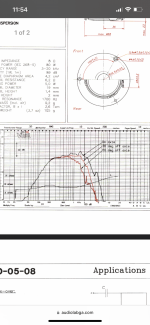
Sometimes the higher frequency phase situation can be a little inaccurate due to the factory plot not measuring the delay differences. Whenever responses are not properly measured they won't include the difference in distance, which you could estimate and apply manually.
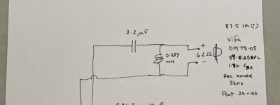
Here. Plus the plot for the two versions of the tweeter, one of which has incorrect x-axisCan you trace out the Sony XO's tweeter filter? We can take a look.
Attachments
That’s what I’m hearing! I’ll swap/add those caps and have another listen.I think I have it (if your schematic is correct). The Sony with the swapped in Seas woofer does this - guess they liked their treble !
And didn't mind a big null.
View attachment 1112551
Is there a “best” place to get audio caps and inductors? I’ve been looking around and it’s hard to get the right values and also not pay a lot of money.
These are a good choice...

or if you prefer something in polypropylene...

Jaycar used to sell well priced inductors but they've been moving away from those. They still sell magnet wire if you want to wind your own.
or if you prefer something in polypropylene...
Jaycar used to sell well priced inductors but they've been moving away from those. They still sell magnet wire if you want to wind your own.
I mainly buy from SpeakerBug. I do avoid esoterica tho
https://speakerbug.com.au/index.php?route=product/category&path=25_28
https://speakerbug.com.au/index.php?route=product/category&path=25_28
Thanks. 500metres from home…These are a good choice...
View attachment 1112621
or if you prefer something in polypropylene...
View attachment 1112622
Jaycar used to sell well priced inductors but they've been moving away from those. They still sell magnet wire if you want to wind your own.
There’s something i don’t understand about this graph. The mid and tweeter both look high at around 7kHz, so what causes the dip?I think I have it (if your schematic is correct). The Sony with the swapped in Seas woofer does this - guess they liked their treble !
And didn't mind a big null.
View attachment 1112551
If the schematic was correct (no low-pass circuit on midband + 2nd order electrical high-pass on tweeter), and the phase derived by the simulator was correct, there is a 180 degree phase-shift from the tweeter at this frequency range compared to the midrange, causing a cancellation.
Without true in-cabinet measurements, the inferred phase may not be what is happening in practice.
Without true in-cabinet measurements, the inferred phase may not be what is happening in practice.
Thanks. I guess that's a case where reversing polarity on either tweeter or midrange is worth trying. I need to find a way to set my source up for a-b comparisons, none of my amps have a mono switch.If the schematic was correct (no low-pass circuit on midband + 2nd order electrical high-pass on tweeter), and the phase derived by the simulator was correct, there is a 180 degree phase-shift from the tweeter at this frequency range compared to the midrange, causing a cancellation.
Without true in-cabinet measurements, the inferred phase may not be what is happening in practice.
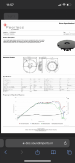
Reading and learning as I go, looking just at the woofer for now. The recommended inductor for this woofer in a 2 way design is around 1.3mH, which at 8Ohms is around 900Hz and is what I already have in the Sony XO, so I was curious about the 3.9mH recommendation here as that equates to around 300Hz and the inductors are over $20ea for that value. I presume that the lower recommended crossover point is because this SEAS woofer has extended range and the inductor circuit has a gentler slope. I have added a 33uF across the woofer to increase the slope, but have not added a resistor. Is the intent of the cap and resistor in this design intended to flatten the impedance, or for increasing the slope, or both? If I follow the other guidance for impedance flattening, based on the woofer specs I get 7.2 Ohms and 4.7uF in series, connected across the woofer.OK, gents. Learned a lot. Here's another go at a sim. As per @shadowplay62's eagle eyes, the old Seas datasheet was already measured in box.
Corrected scale of the old D19 datasheet. Applied baffle diffraction to mid and tweeter, though it seems to do little in their bandpass regions.
Ended up bass-mid XO @700hz LR2-LR2, and mid-tweeter XO @3.5khz LR4-LR4, cause the D19 doesn't easily fit BW3. Mid + tweeter inverse polarity.
Hope this helps!
View attachment 1111848
What frequency are you trying to cross the woofer? Does the few25 file linked to earlier include the baffle step?
I believe the FEW file is in box, I’m trying to cross around 900hzWhat frequency are you trying to cross the woofer? Does the few25 file linked to earlier include the baffle step?
The response is what counts. Looking at what it would do on it's own is a good cross check but there are too many variables.so I was curious about the 3.9mH recommendation
Ok, perhaps it could be fudged a little smaller. This is an intermediate Q second order target...
It may or may not necessarily fit into the overall crossover plan.
Reducing the slope compared to L and C, and modifying the Q.Is the intent of the cap and resistor in this design intended to flatten the impedance, or for increasing the slope, or both?
Given While I am waiting for parts, since the response is so flat for the woofer, I put the Sony one back in (10uF/1mH, around 1500Hz high pass for the tweeter) but added a 33uF across the woofer to take it down a bit and also a 4.7uF across the midrange and reversed the polarity. It sounds less harsh than before but I think it needs 12dB slope on the top of the mid range.
You can't build a crossover without a measurement microphone.
Manufacture spec sheets are completely useless for modelling.
A umik1 is $80, it will last a lifetime, be all the mic even the most advanced hobbyist will ever need and be useful regardless of DIY intentions for room correction.
I can promise, that if you built any of your designs from modelled specs and manufacture datasheets, and then measured it, it will be WILDLY different.
I can see that you've put a lot of time ino the project, and don't want to disparage you, what I want is for you to be happy and confident with the end result, and save you some money on cycling through endless passive components trying to blindly get something that sounds "right"
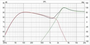
The response attached, is what happens if you model a pair of the very highly regarded jeff bagby adelphos speakers using the manufacturers specs, and that's using super high quality and linear drivers known to be very consistent with their published parameters. Your results are likely to be exponentially worse.
Manufacture spec sheets are completely useless for modelling.
A umik1 is $80, it will last a lifetime, be all the mic even the most advanced hobbyist will ever need and be useful regardless of DIY intentions for room correction.
I can promise, that if you built any of your designs from modelled specs and manufacture datasheets, and then measured it, it will be WILDLY different.
I can see that you've put a lot of time ino the project, and don't want to disparage you, what I want is for you to be happy and confident with the end result, and save you some money on cycling through endless passive components trying to blindly get something that sounds "right"
The response attached, is what happens if you model a pair of the very highly regarded jeff bagby adelphos speakers using the manufacturers specs, and that's using super high quality and linear drivers known to be very consistent with their published parameters. Your results are likely to be exponentially worse.
Attachments
I remember that comparison. Do you have a link to the original thread? I think there was more to it than meets the eye.
I'm not sure you do remember this exact comparison as it's one I did myself and haven't posted about on here 😂I remember that comparison. Do you have a link to the original thread? I think there was more to it than meets the eye.
- Home
- Loudspeakers
- Multi-Way
- Interdyn and SEAS drivers and crossover combination