@motokok don't worry about it. The shape will be correct even if the level is different, and the absolute level doesn't really matter as long as it is the same for all three ways, which it will be if you use a baffle curve from the same program, and the same scaling, for each way.
The only reason I even suggested scaling is so they appear readily on the plots without you having to adjust them. This may not be necessary and if you have any doubts, don't scale them at all.
It seems the Edge and Vituixcad are made in reference to full-space radiation and Jeff Bagby's Diffraction Spreadsheet is made in reference to half-space. The only difference is a clean 6dB change in level which isn't a problem.

The shape will be correct even if the level is different, and the absolute level doesn't really matter as long as it is the same for all three ways, which it will be if you use a baffle curve from the same program, and the same scaling, for each way.
Smacks foreheard. Thanks, I think I get that (where all ways are adjusted the same, only the relative levels then matter)
530mm H x 230mm W. There is a raised step on the edge that the grill sits inside of.I read the sticky design without measurements opening thread again and it doesn't really say how to deal with it rather than describe the phenomenon.
Eyeballing the photo, the cabinet front baffle is approx 464mm H and 308mm W.
Attachments
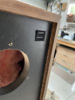
230mm W from outside edge to outside edge? I thought the datasheet says the diameter of the woofer is 261mm?530mm H x 230mm W. There is a raised step on the edge that the grill sits inside of.
Sorry, typo. 280mm wide, edge to edge inside the trim.230mm W from outside edge to outside edge? I thought the datasheet says the diameter of the woofer is 261mm?
The seas datasheet says that the curve is already measured in 4pi in a 28L cabinet, so you do not need to consider any baffle step response.No, I don't know how to do that yet, but would like to learn.
I know how to model the diffraction curve from Basta, but don't know how to apply (subtract) it to/from the datasheet curve + simulated filter.
Below you can see the overlay of your traced curve and the bass response for a cabinet of 28L calculated in VCad Enclosure tool.
PS
If you need to include the baffle step response in your bass response, just export it from Diffraction tool and load the response in the Align tab of the Enclosure tool.
I did contact him - he no longer has a “crossover guy”, but uses a third party now.Is Aranmar Acoustics in Melbourne still around - I understand they built several speakers in Interdyn's range; they certainly built my 'Pee Wee Monitors'. If they are around, they might be able to assist if you ask nicely.
Geoff
OK, gents. Learned a lot. Here's another go at a sim. As per @shadowplay62's eagle eyes, the old Seas datasheet was already measured in box.
Corrected scale of the old D19 datasheet. Applied baffle diffraction to mid and tweeter, though it seems to do little in their bandpass regions.
Ended up bass-mid XO @700hz LR2-LR2, and mid-tweeter XO @3.5khz LR4-LR4, cause the D19 doesn't easily fit BW3. Mid + tweeter inverse polarity.
Hope this helps!
Attachments
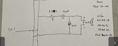
Not sure what you mean by an asymmetric crossover. The woofer has a single series 1.3mH inductor for a low pass, if I use 8 ohms that suggests a low pass around 900 Hz. The mid range has an LC high pass where the inductor is around 1200hz and the cap is 5kHz, no low pass, and the tweeter also has a high pass where the inductor is around 5khz and the inductor is 9khz. I don't know how these combine in the same circuit, or if the nominal 8 ohms should be used to estimate rather than the dc resistance , eg 6.3, 5.4 and 5.8 for these speakers. I find it strange that a large multinational like Sony could build something that seems so off, especially if they went to the trouble of sourcing danish drivers.If it's an asymmetric XO then having what appears to be different crossover frequencies makes sense. The slope on the driver with a single element pass is shallow compared to the driver with the two element pass; it is the combination that counts.
Trace out the individual response of each driver and see if they meet at a -6dB point
An Asymmetric crossover is one where the different drivers have different acoustic slopes.
Some drivers need shallow slopes; a single element or 6dB, some need no components like the Vifa P-13s I use; some need three or four components like the tweeter 4th order motokok has given you above
You don't use the DCR or the nominal impedance except as a general indication, what you need to use is the impedance at the desired XO point,
Personally I would assume that Sony knew what they were doing and used the closest nominal value component
ok thanks. It’s going to take me a while to source parts and assemble a new crossover so I am curious to understand a bit more about what I already have. I will look up the charts and recalculate what the crossover frequency would be, but is there any guidance on how a cap and inductor will interact if they are in the same circuit but having different frequency characteristics. Is it just additive?An Asymmetric crossover is one where the different drivers have different acoustic slopes.
Some drivers need shallow slopes; a single element or 6dB, some need no components like the Vifa P-13s I use; some need three or four components like the tweeter 4th order motokok has given you above
You don't use the DCR or the nominal impedance except as a general indication, what you need to use is the impedance at the desired XO point,
Personally I would assume that Sony knew what they were doing and used the closest nominal value component
The way crossovers work is described in the basic books on the subject. These basic books might cost you a bit of money. I don't understand the mathematics well enough to try and explain them
A capacitor and inductor resonate, and this working together has definable characteristics. The driver is a 'load' on the resonance that takes energy from it, and forms part of how it can be characterised.
If there's a part of a particular circuit you'd like explained, just ask.
If there's a part of a particular circuit you'd like explained, just ask.
Thanks. So for the example attached, I understand the resistor will reduce the absolute level. If I look at the speaker inductance on the plot, it is between 7-8 ohms from .5-3 khz. If I look up a 10uF capacitor at 8 ohms the frequency cutoff is 2 kHz, for a 1mH inductor it is 1200 Hz. Does that mean for this circuit there is a sharper attenuation curve below 1200 hz, starting to flatten at 2khz? And there is no low pass element at all.A capacitor and inductor resonate, and this working together has definable characteristics. The driver is a 'load' on the resonance that takes energy from it, and forms part of how it can be characterised.
If there's a part of a particular circuit you'd like explained, just ask.
Attachments
I'm not sure which example you're referring to, I had some concerns about some of the posted schematics so I'm not wanting to guess.
In any case, 1mH and 10uF resonate at 1600Hz. They do more than just work on their own. Their relative phase keeps the energy between them and they can even create an output level higher than the input (just to make a point). Examples of resonance...

In any case, 1mH and 10uF resonate at 1600Hz. They do more than just work on their own. Their relative phase keeps the energy between them and they can even create an output level higher than the input (just to make a point). Examples of resonance...
@Kevviek I applied your written high-pass filter to the K10 - it models thus - not sure what they were trying to do, TBH - closest acoustic response is roughly LR2 about 1100hz that loses precision within 1 octave.
No low-pass gives...I have no idea - this doesn't match anything - so I struggle to see how they hoped for good blending with the troublesome D19 with its very high resonance frequency of 1750hz. Maybe borne out by an irritating treble as you said.
Red = unfiltered K10, Green = K10 + Sony filter, pink = textbook curve
Last edited:
I added the pics a moment later but you have answered my question. I assume then that if I increased the capacitor to say 22 or 33uF, with that same inductor, the resonant frequency would be closer to the target 800hz.I'm not sure which example you're referring to, I had some concerns about some of the posted schematics so I'm not wanting to guess.
In any case, 1mH and 10uF resonate at 1600Hz. They do more than just work on their own. Their relative phase keeps the energy between them and they can even create an output level higher than the input (just to make a point). Examples of resonance...
View attachment 1112511
That's right, and the resonance would increase the response at the knee. The resistor and the driver are both damping that resonance. The resistor contribution is not necessarily flat across the spectrum.
Thanks - I think this explains what I am hearing…the low pass on the SEAS driver may be a little bit higher than ideal but is helped by the driver plot, but for the mid and tweeter I am getting the worst of both worlds. It’s going to take me a while to assemble the new crossovers but I might try increasing the 10uF to 22 on the K10, the 2.2uF to 6.8 on the D19, and add a 4.7uF across the K10 as a high cut in the interim.@Kevviek I applied your written high-pass filter to the K10 - it models thus - not sure what they were trying to do, TBH - closest acoustic response is roughly LR2 about 1100hz that loses precision within 1 octave.
No low-pass gives...I have no idea - this doesn't match anything - so I struggle to see how they hoped for good blending with the troublesome D19 with its very high resonance frequency of 1750hz. Maybe borne out by an irritating treble as you said.
Red = unfiltered K10, Green = K10 + Sony filter, pink = textbook curve
View attachment 1112513
- Home
- Loudspeakers
- Multi-Way
- Interdyn and SEAS drivers and crossover combination